![]()
![]()
RT-FF01 - PCB for building clones and mods of the Fuzz Face distortion pedal.The RT-FF01 is a pcb for building or experimenting with the Fuzz Face circuit; it can be used to make a near-exact clone with PNP germanium transistors and positive ground, or a more modern variant with NPN silicon or germanium transistors and negative ground. In addition there are positions on the pcb for some components which are often suggested as mods by Fuzz Face experts. The PCB has a position for an LED indicator which can be omitted if not wanted. The pot connections can be used for pcb mounted pots or wire connections. Full-bypass switching is recommended so there is also a position for a pull-down resistor at the input to avoid clicks. |
|

|
Dimensions 22 x 52 mm.
Price £6.50 with free p&p in UK. £3.50 p&p for ROW. |
|
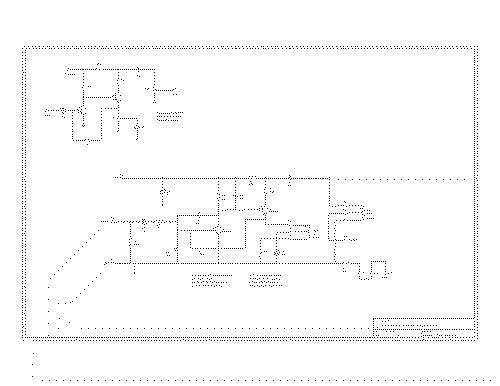
Click image for pdf An interesting circuit, the low input impedance makes it very sensitive to the guitar volume control. The original designer made no allowance for the poor quality of the germanium transistors that were used. But it is an accurately designed circuit, and tends to come up with about half the supply voltage on the collector of Q2. It is a simple linear amplifier, and the fuzz effect is the result of overdrive clipping. There is a misconception that it has some sort of built-in assymmetry, this may be due to the transistors that were originally used being a lot less than perfect. I would recommend construction using NPN silicon transistors with the normal negative ground. It is a lot easier than trying to get ancient germanium transistors to work, and the sound quality of the fuzz is better. I have seen it described as more harsh and aggressive and also less harsh and aggressive than germanium versions. There isn't really much difference, and these contradictory opinions are probably caused by the extreme variabilty of the original Fuzz Faces. |
|
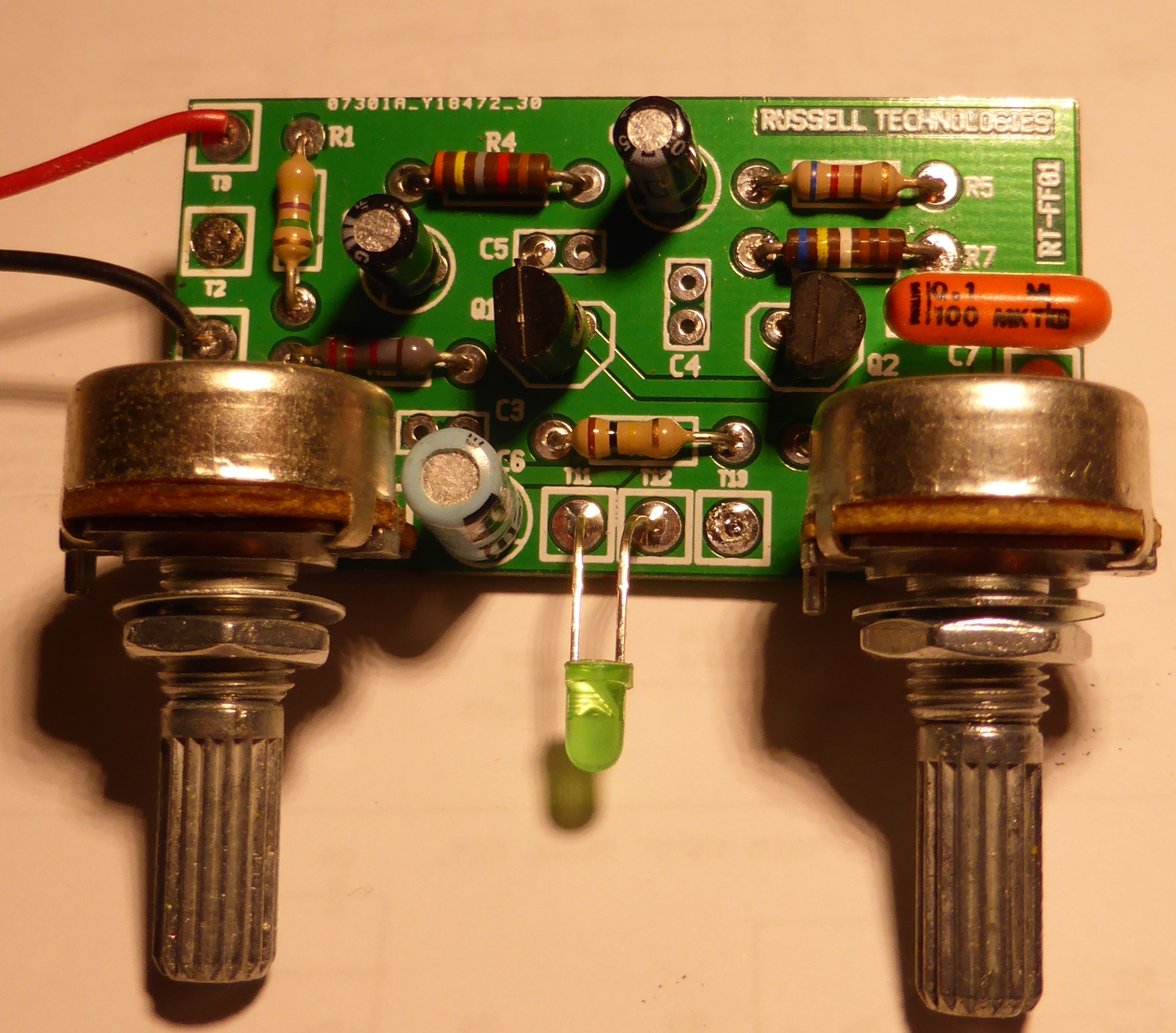
Simple negative ground version built with silicon NPN transistors and pcb-mounted pots, fitted with optional LED. None of the optional mod components fitted. |
|
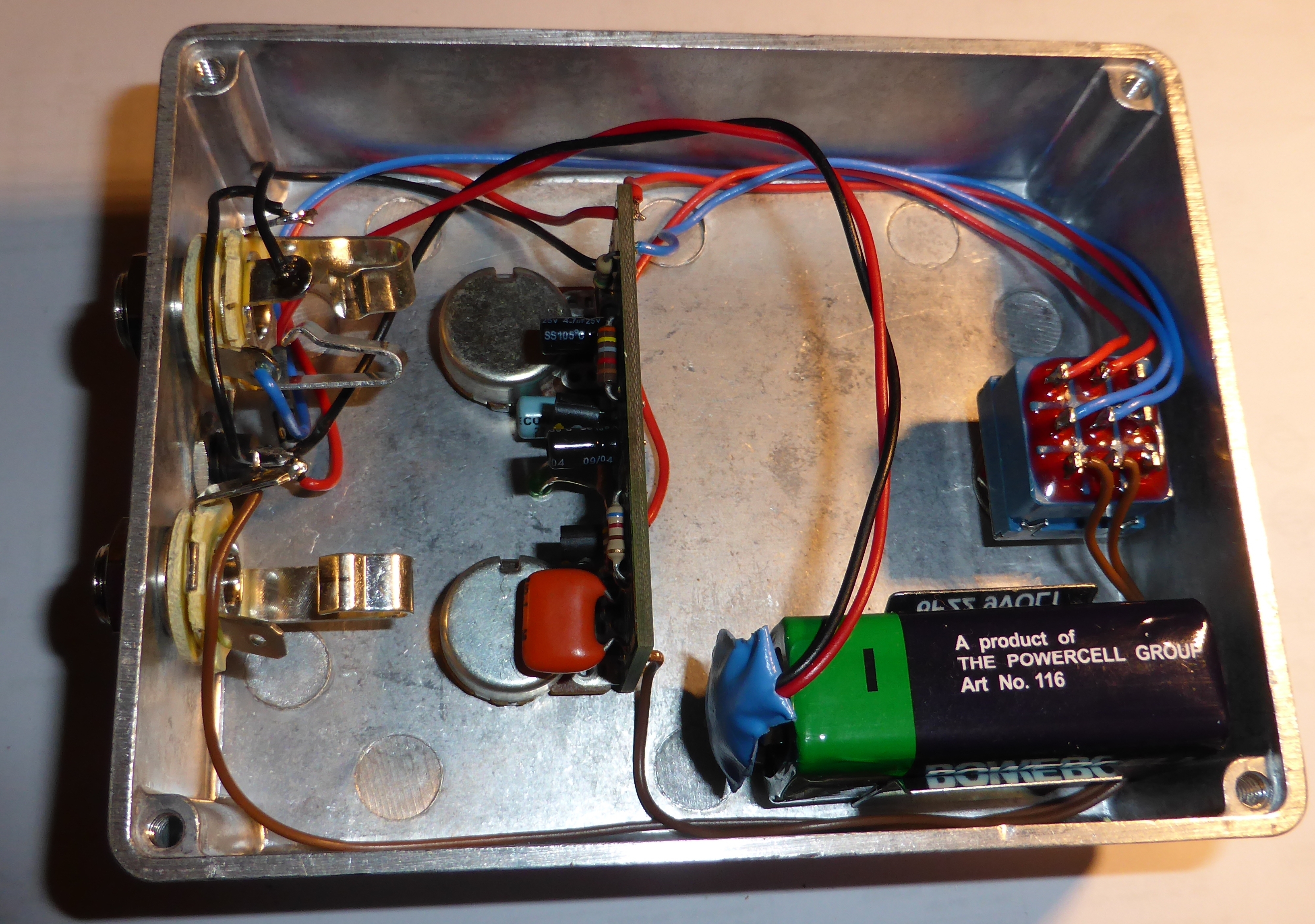
A prototype built into a standard sized diecast box. A power socket is fitted between the input and output jacks with a series diode to protect the battery. |

|
This type of jack makes a good connection to the metal case. |
|
|
|
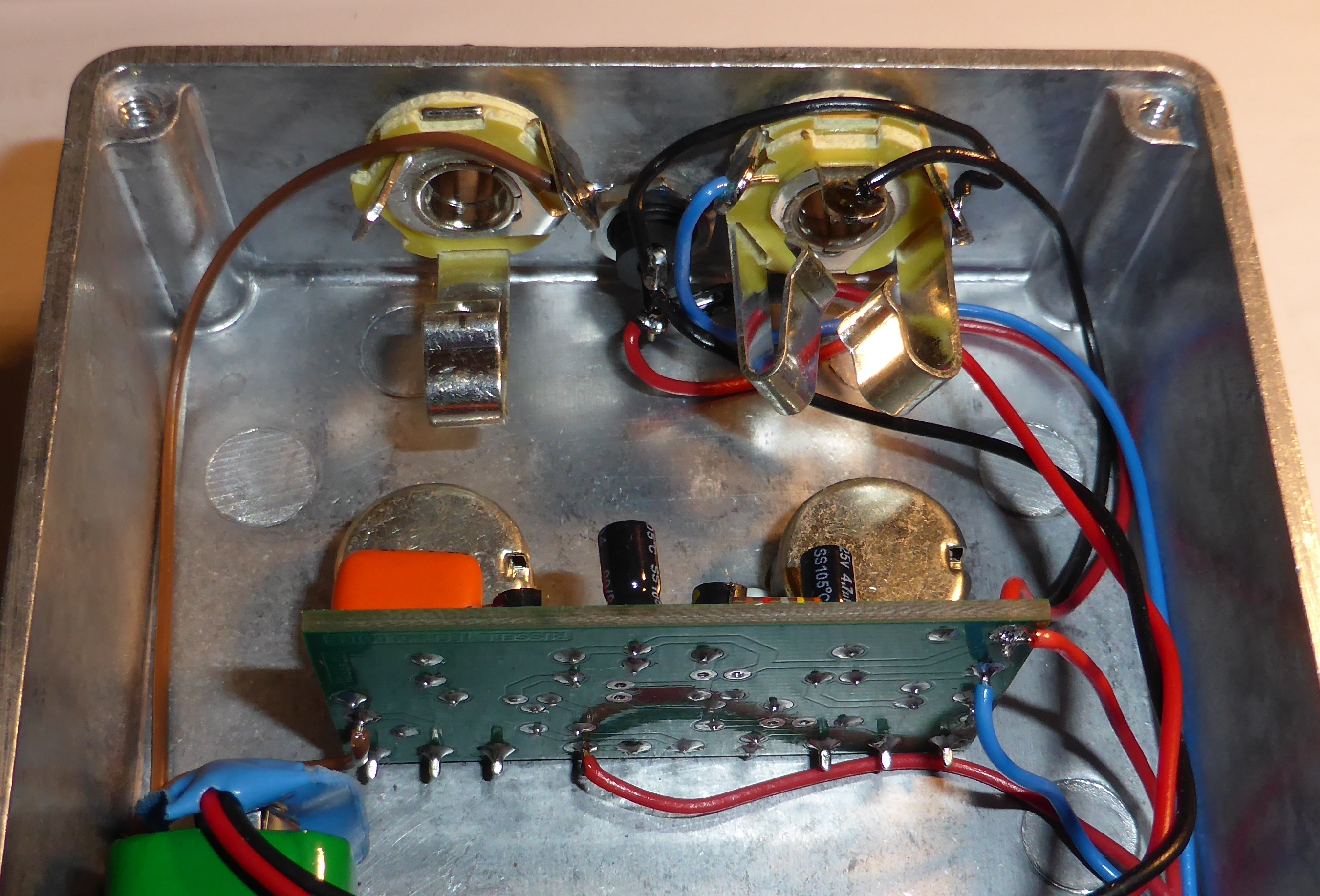
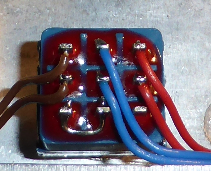
Three-pole changeover switch wired for true bypass and LED indication. |

|