![]()
![]()

|
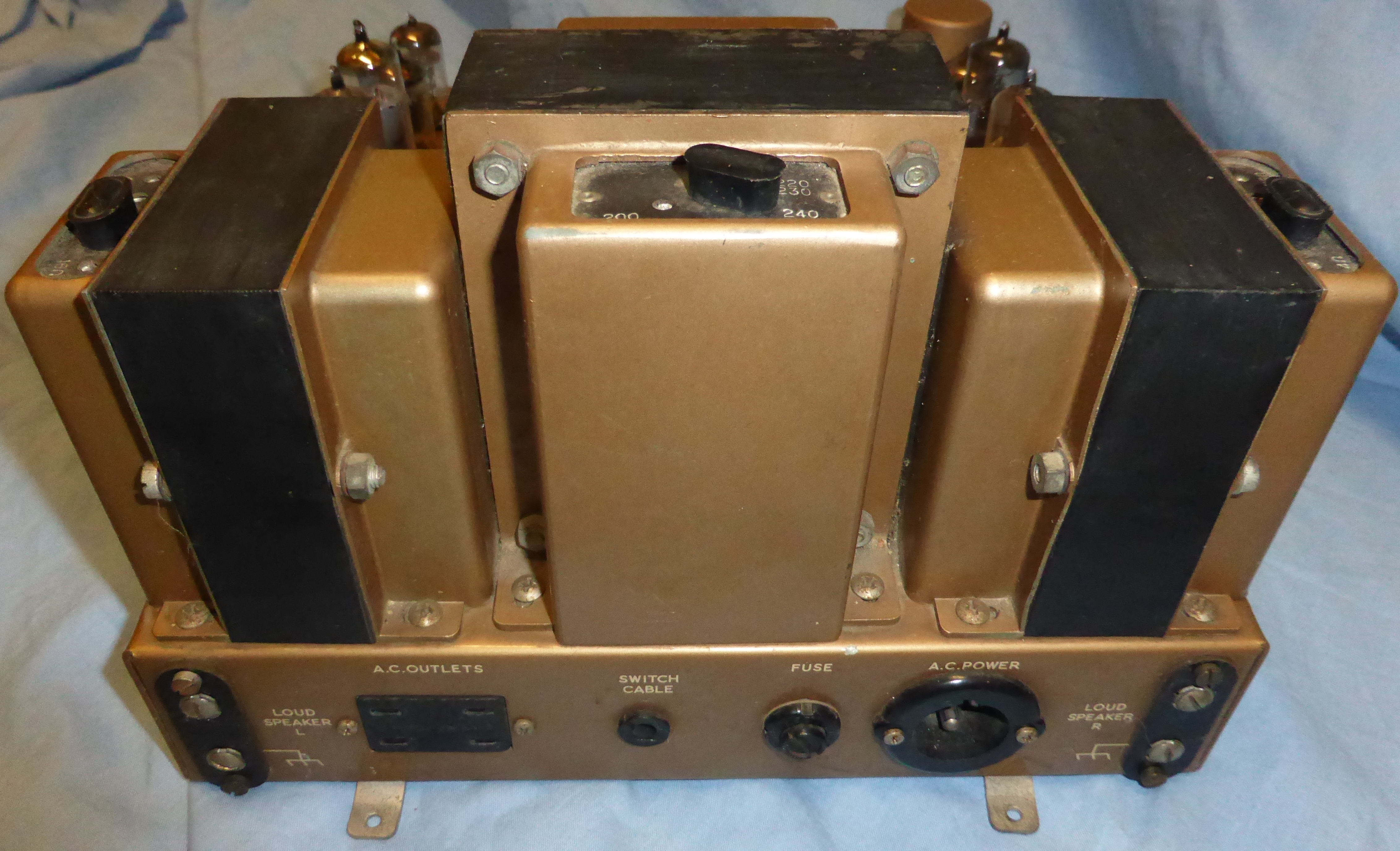
Another of my favourite amps, these have very good specs for valve amps of the time and they sound excellent with a pair of efficient speakers. Twenty watts is a little underpowered for many modern less efficient speakers, but they still sound good.
|
A few pictures of a Stereo 20 in original condition. |
|

|
If you want to embiggen any picture here or on other pages, right-click on it then select view image. Or whatever your browser calls it. |

|
|
|
|

|
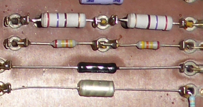
Here you can see the safety resistor R21 (100/3W) as it should be. It is rated so that the solder will melt if overcurrent faults occur. To repair, 60/40 or eutectic will be OK. To replace, you have to judge the thermal characteristics of the replacement. Good luck. |

|
My redrawing of the schematic. The original is a nice drawing, with some very attractive features of the style of the period, but many copies on the web are a little fuzzy and difficult to read, so I thought it might be worthwhile doing this more modern style version. I hope it is useful to somebody.
This image is a png file. To see full size, right-click>view image, then click on image or ctrl-scroll to adjust size. Best printed at A3 size, but A4 will work if you have a good printer and eyesight. For A4 size pdf click here For A3 size pdf click here For zip file of installation and maintenance manual click here Keith Snook has an interesting discussion of the Leak amplifiers here |

|
I found this example of a repair done by a bad person on the interweb. Notice how it looks all wrong. Bad cans should be gutted and refilled in my opinion, not replaced by blue things. |
| Here are a few pics of another specimen, which I am going to repair. | |

|
It doesn't look too bad. The paint splatters will clean off. |

|
Some hooligan has drilled a hole in the back panel. |

|

|

|
There are some defects in the paintwork.
|

|
So following my usual conservative approach, I have done little more than what is necessary to get it working properly to within its original spec or better, and check that it is electrically safe as much as it ever was. As you can see, these amps were not designed by someone who was afraid of dead children cluttering up the place. (Yes I know they were usually in cabinets)
|

|
Some things I am going to improve even though it's not strictly necessary are the output terminals. The Leak ones are just crap. I don't know what they were thinking, the sort of combined 4mm socket/binding post that I am using here were available in 1963.
|

|
I will keep the original terminals and screws with the amp, someone may one day want to put them back, and they are unobtainium. It might be more appropriate to bury them at a crossroads, but people are funny. |

|
Doesn't look too bad in my opinion. I don't know what to do about the big hole. Maybe put a plastic plug in it. Or leave it for the next owner to worry about. |

|
The capacitors in the output stage. I have decided to leave these alone. They look all wrong but they are fair quality, much better than the originals. Another thing for someone else to worry about. |
|
Here I have made a few changes. The 270 ohm cathode resistors run at a constant 0.5 watts, which makes them very hot, so I have replaced them with 3 watt types. They are still going to get fairly warm.
|

|
I have left in place the first to second stage coupling capacitors, again these look wrong but they are good and very much better than the originals. The small capacitors around the negative feedback tackle check out fine. The old green electrolytics have been replaced with some nice blue Philips ones with a higher rating.
|

|
Works well, mission accomplished. Here you can see it having a go at some Pink Floyd. |
end