![]()
![]()
|
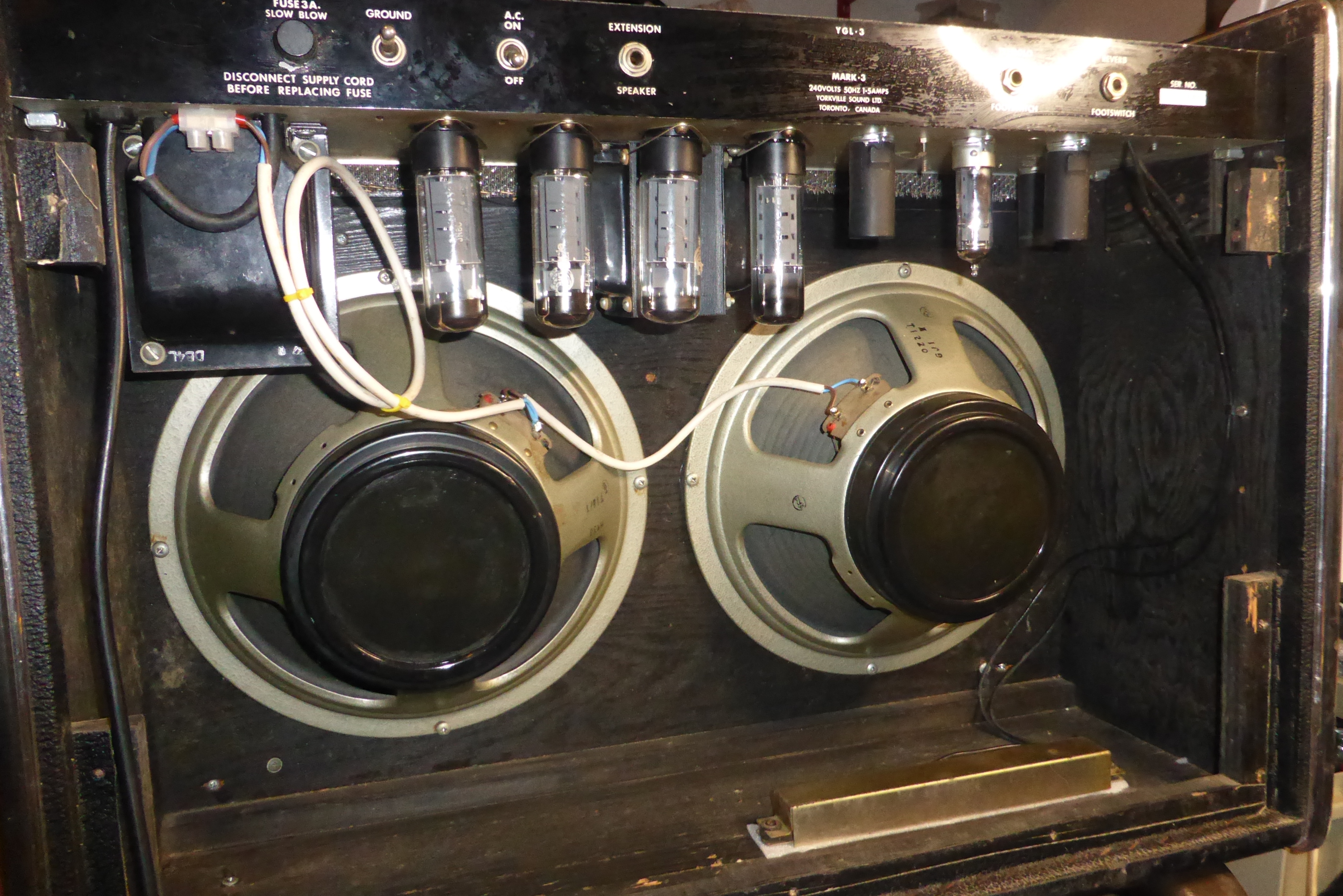
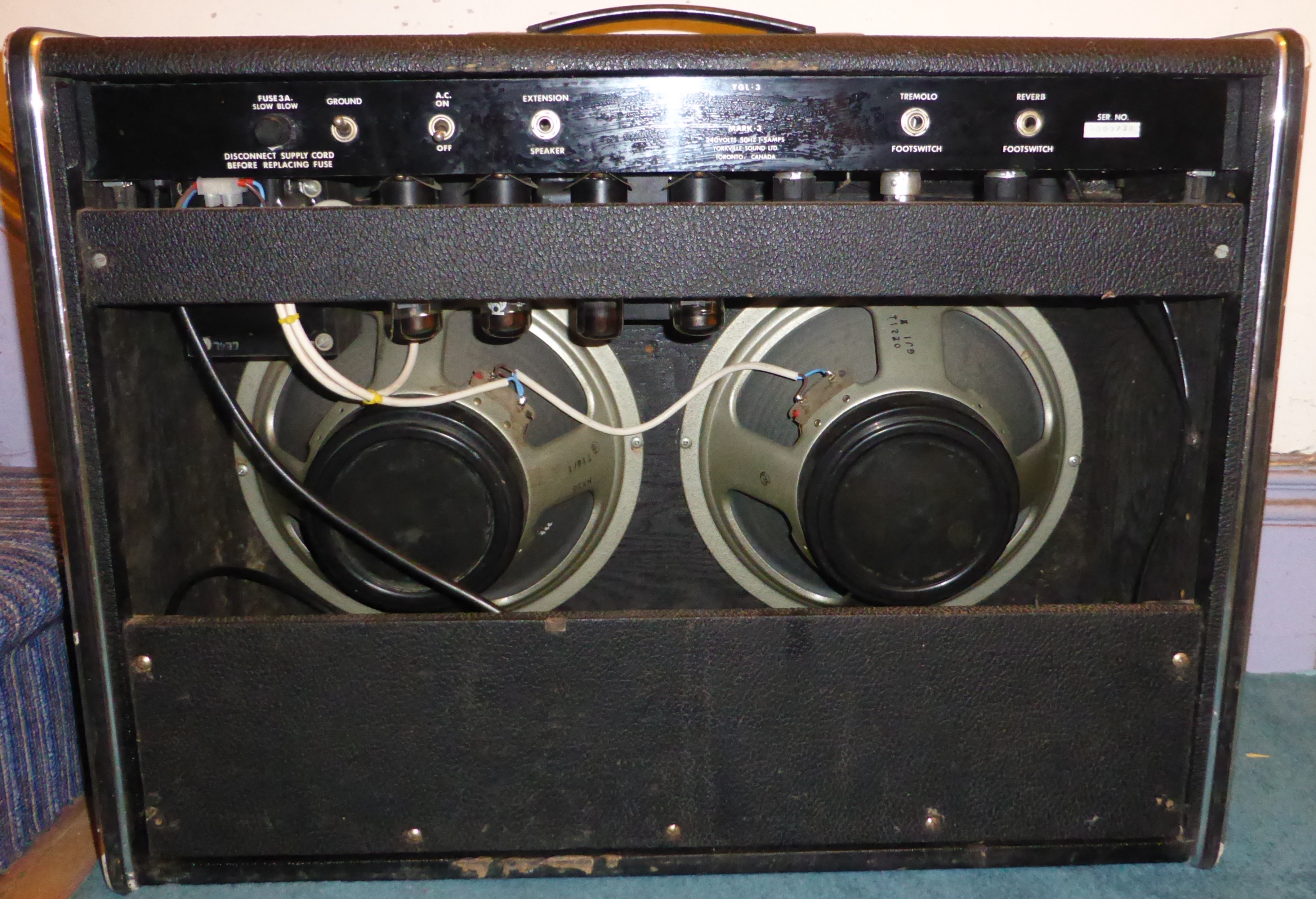
A high-power guitar combo amp, built in Canada by Yorkville Sound Ltd.
|
|
This amp was bought at auction, will be repaired and probably sold. It's nice but I have enough amps, this will be more suitable for a serious guitarist than me.
|
|
Schematic circuit diagrams |
|
|
Main amplifier schematic. This image is a png file. To see full size, right-click>view image, then click on image or ctrl-scroll to adjust size. Best printed at A3 size. |
|
The amp is fitted with a 3-core power cable properly connected for use in the UK, but still has a grounding switch with a deathcap fitted. So I snipped that out, also replaced the 3-core and plug. |
|
The noise was due to failure of the higher-voltage capacitors, particularly the Mallory dynamite duals. A check of the lower-voltage caps showed them all in very good condition, literally working as well as new ones. So I decided to restuff the Mallory ones. |
|
Uncrimping the paper sleeve lets it slide off easily. |
|
And uncrimping the can gets access to the interior loveliness.
|
|
The core is held in by special electronic tar or bitumen like substance. After heating it up the core pulls out easily. If you try this be aware the tar is highly carcinogenic. |
|
Two capacitors ready to go back in. This needs good joints and careful insulation, but fortunately it doesn't have to look nice. |
|
The wires are stuck through holes drilled in the original terminals. |
|
After crimping it all back together and soldering the wires. |
|
It's really not easy to tell it has been messed with. |
|
A new cap fitted to the bias stuff. Bias is easy to adjust, not twitchy at all, but there is no balance adjust. I think I would add one if I was keeping the amp. |
|
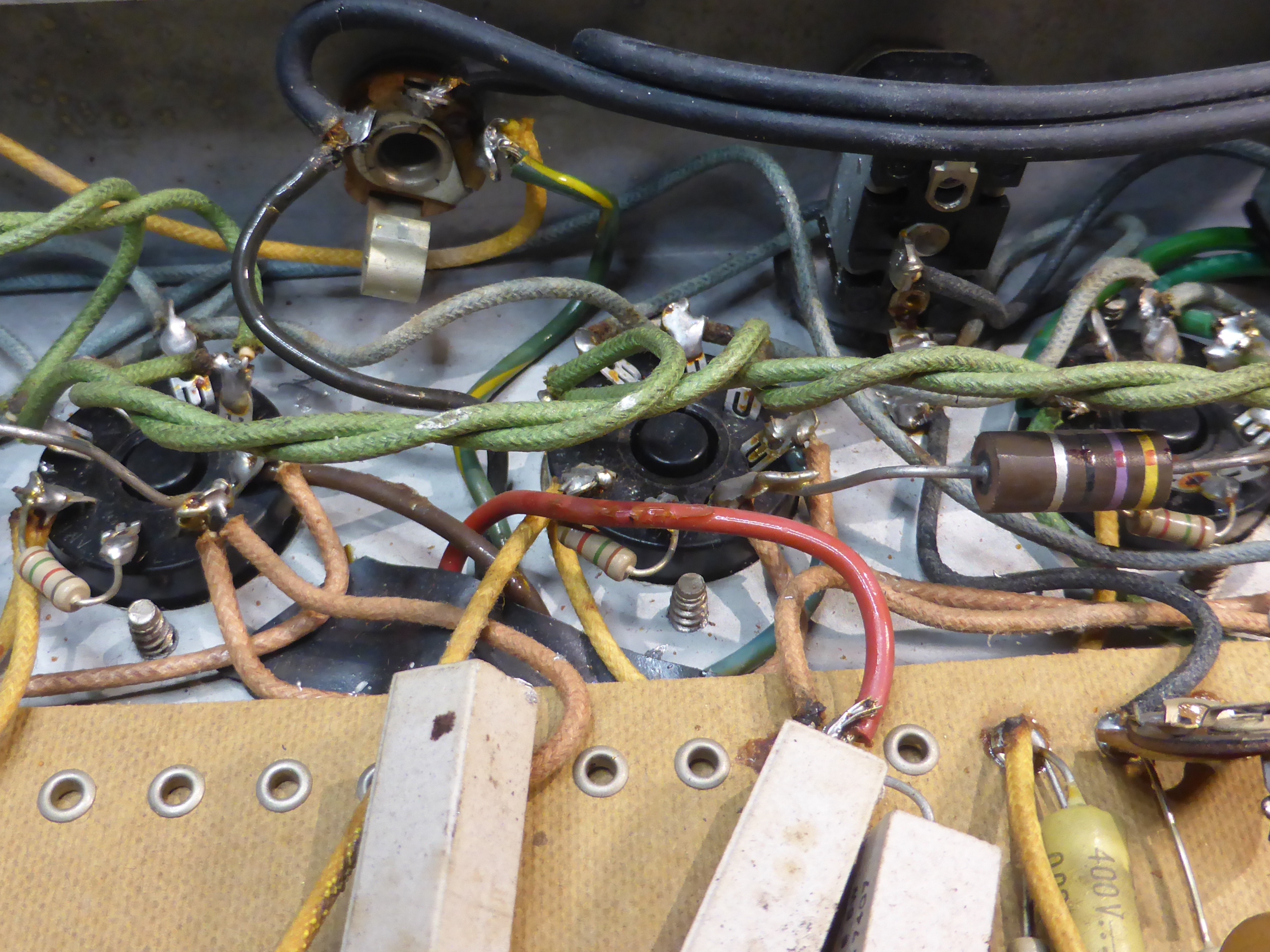
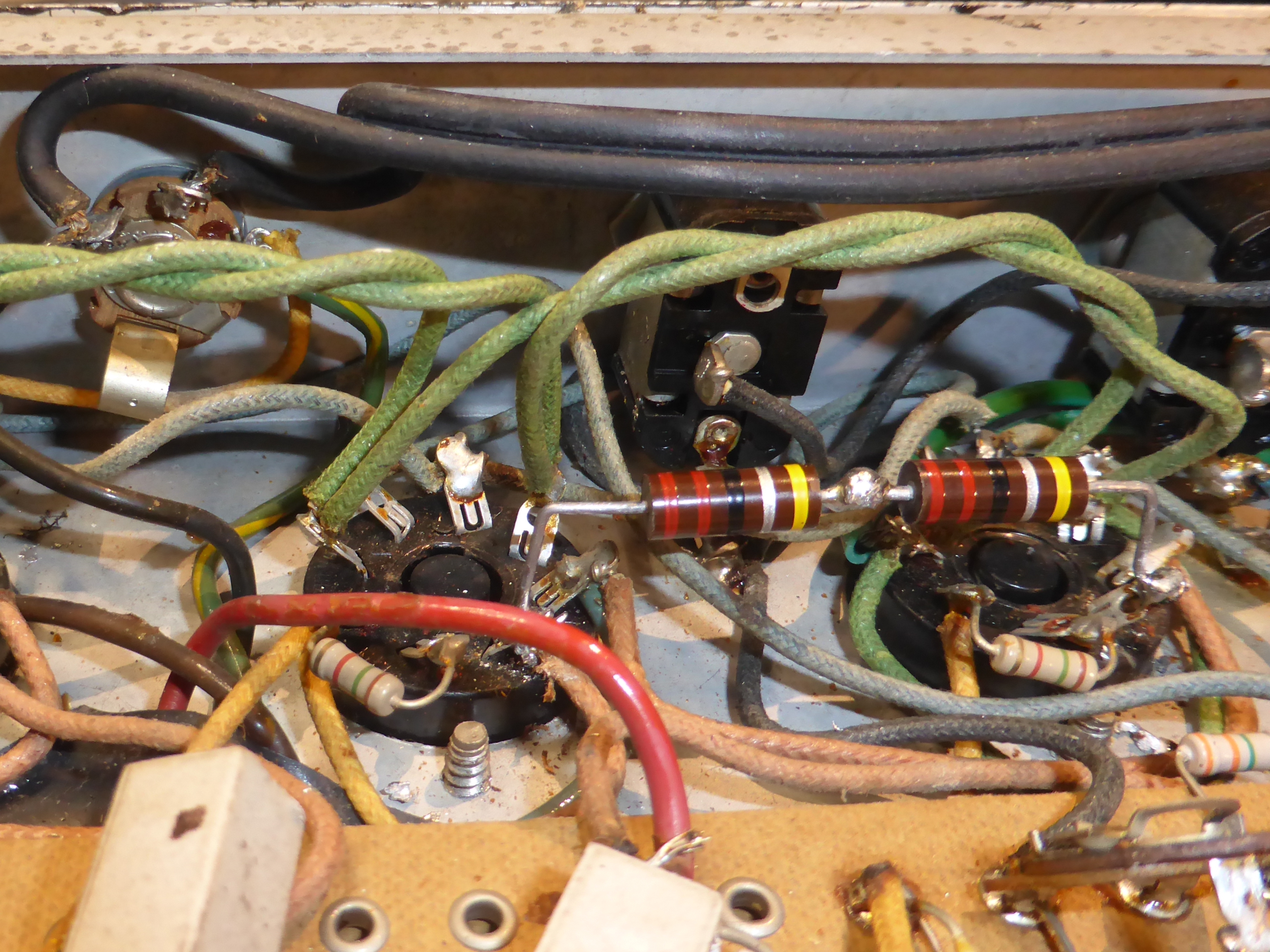
The 47 ohm resistors in the screen circuit are the only other faulty components. Some very slight burning is present, they are just a little undersized. |
|
I have replaced each of the original 47 ohm resistors with a pair of 22 ohm in series. |
|
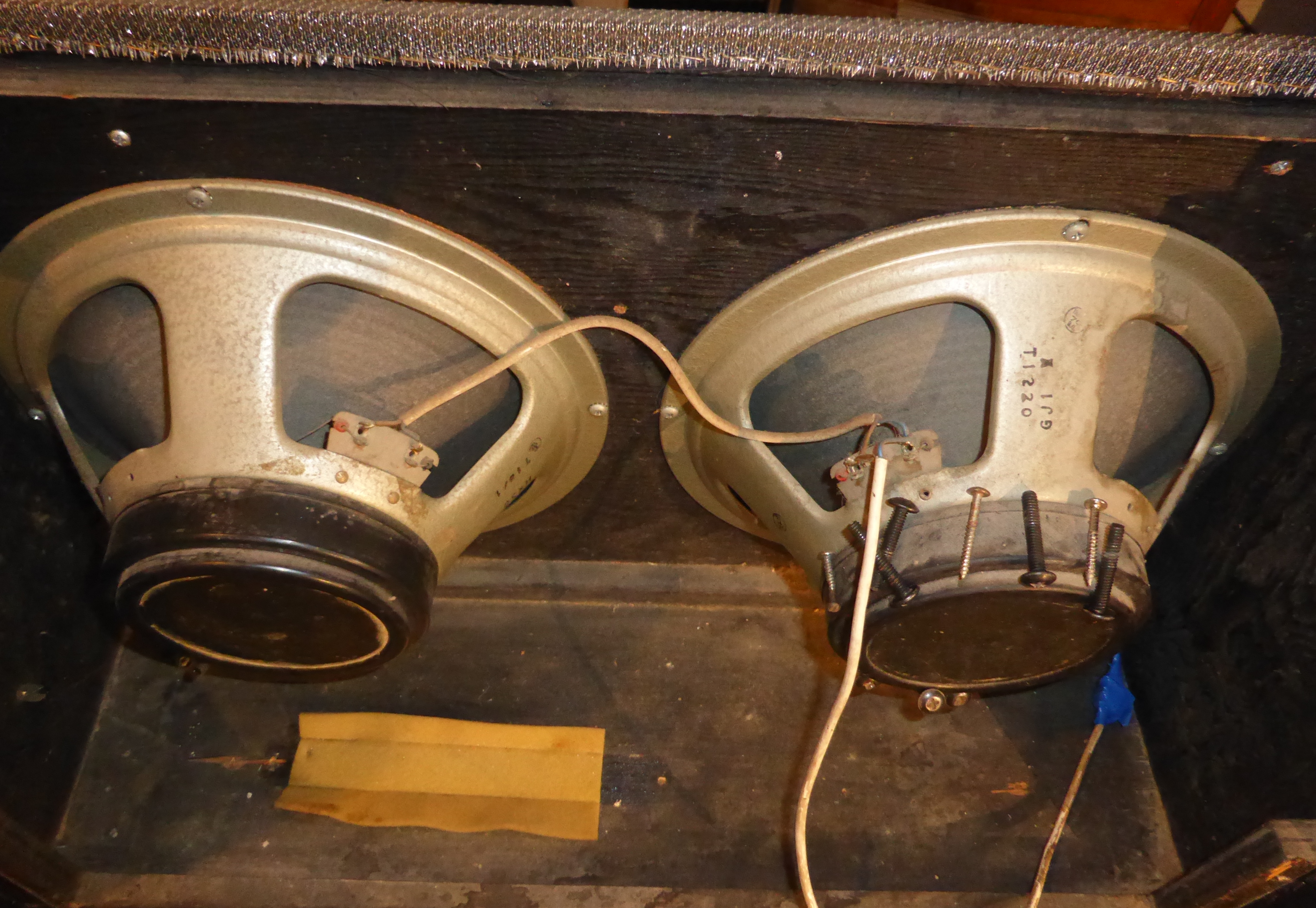
A nice pair of Celestion T1220's under the dust. These turned out to be in excellent condition. Traynor fitted some speakers which were not well liked in many of these amps, so this one was made after they gave it a rethink. I see the date code is 1974, which fits, so these are very likely original. I think it was Capt. Stanley Mullard who said "Them Celestion greenbacks are really nice". These ones are black though, which is obviously loads better.
|
|
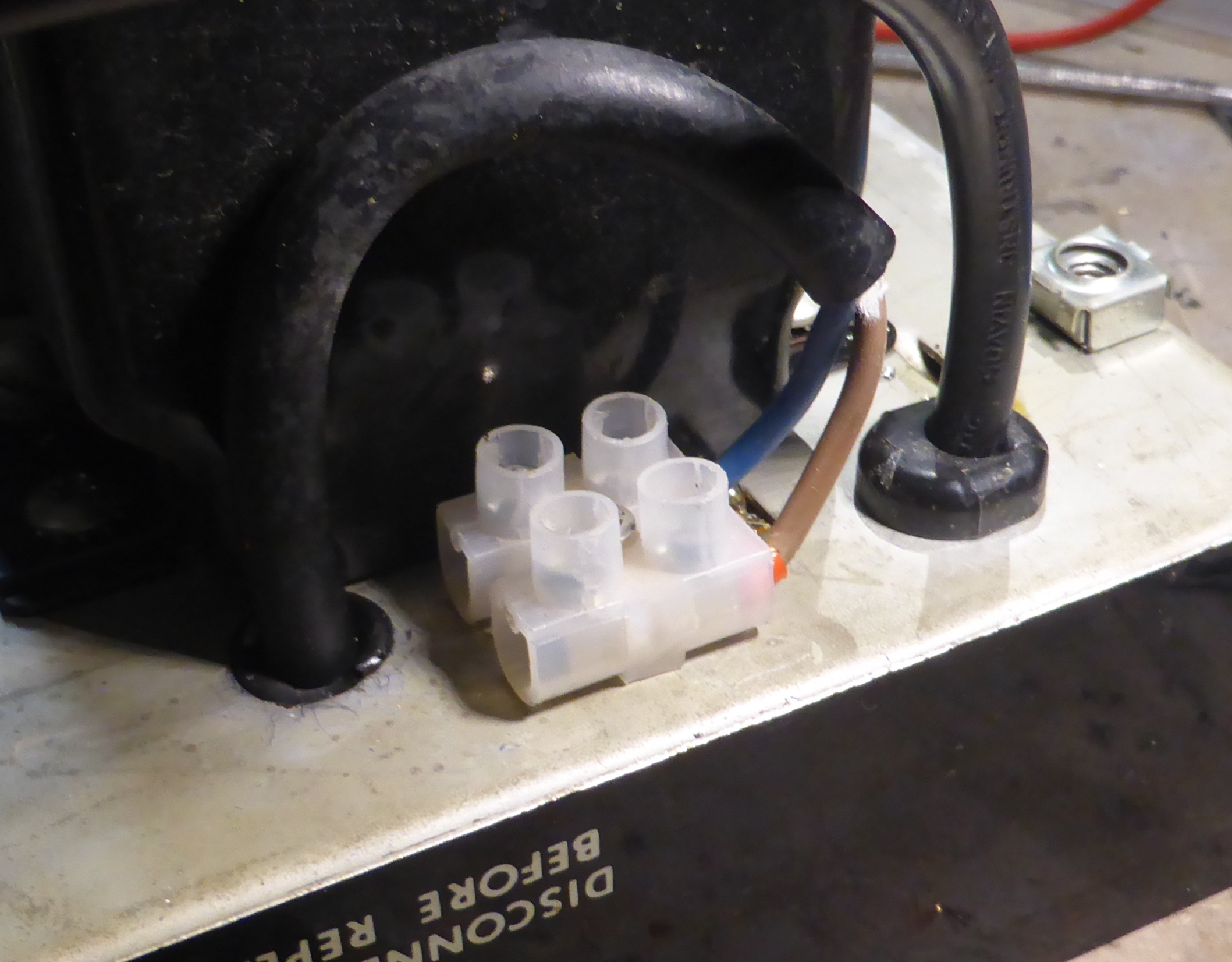
I have put a terminal block on the speaker output, I think it's better to be able to disconnect the speakers easily if the chassis ever needs to be taken out. |
|
Partially reassembled after a bit of cleaning. I have found some valve covers, which were missing when I got it. |
Some observations on the clockwork |
|
|
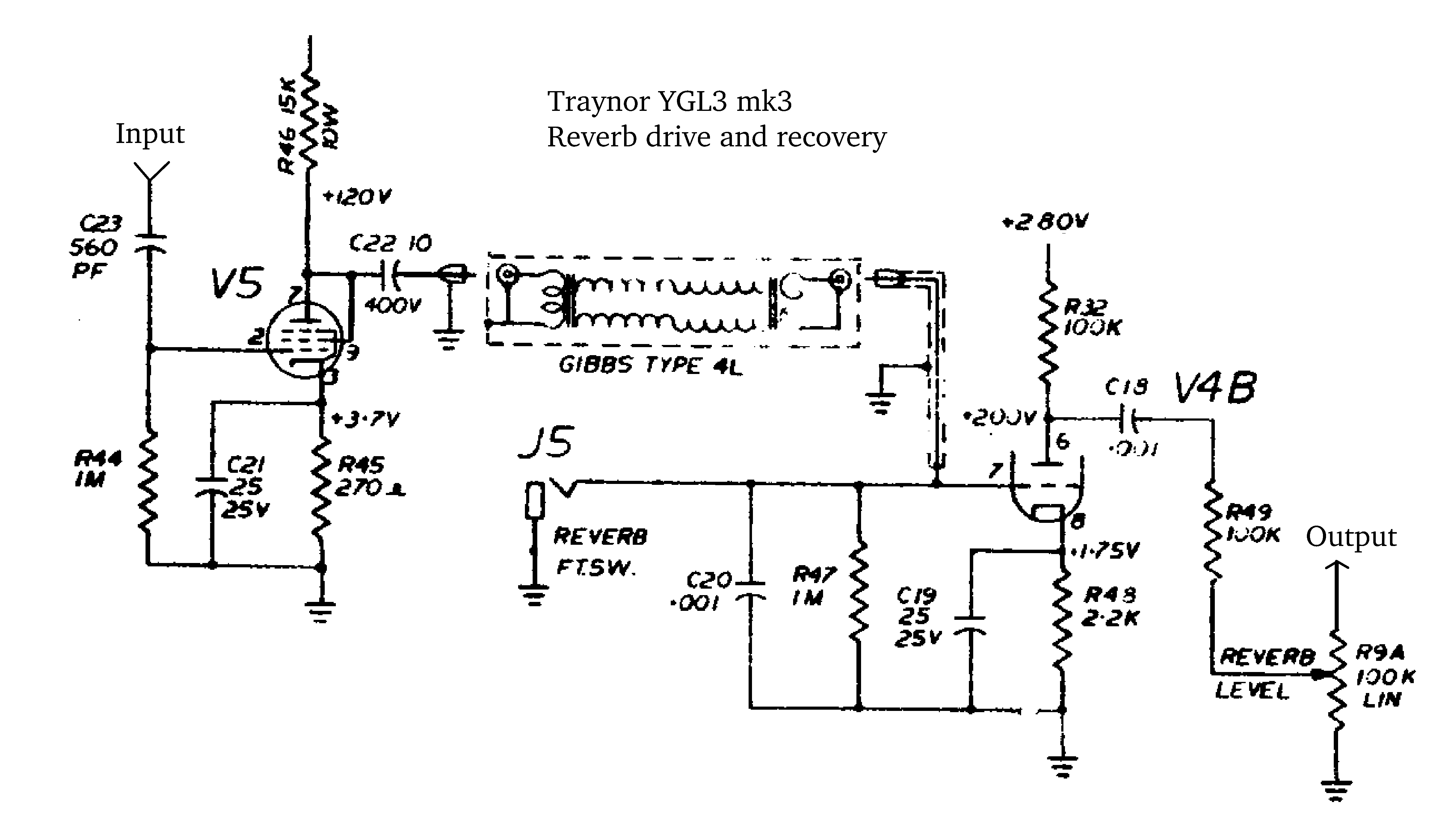
The reverb is unusually driven by the anode of the pentode V5, without an impedance-matching transformer. The reason for this arrangement is not clear to me, it may just be cost-saving, although the amp is not built cheaply. It requires the use of another large high-voltage capacitor. The recovery is conventional.
|
|
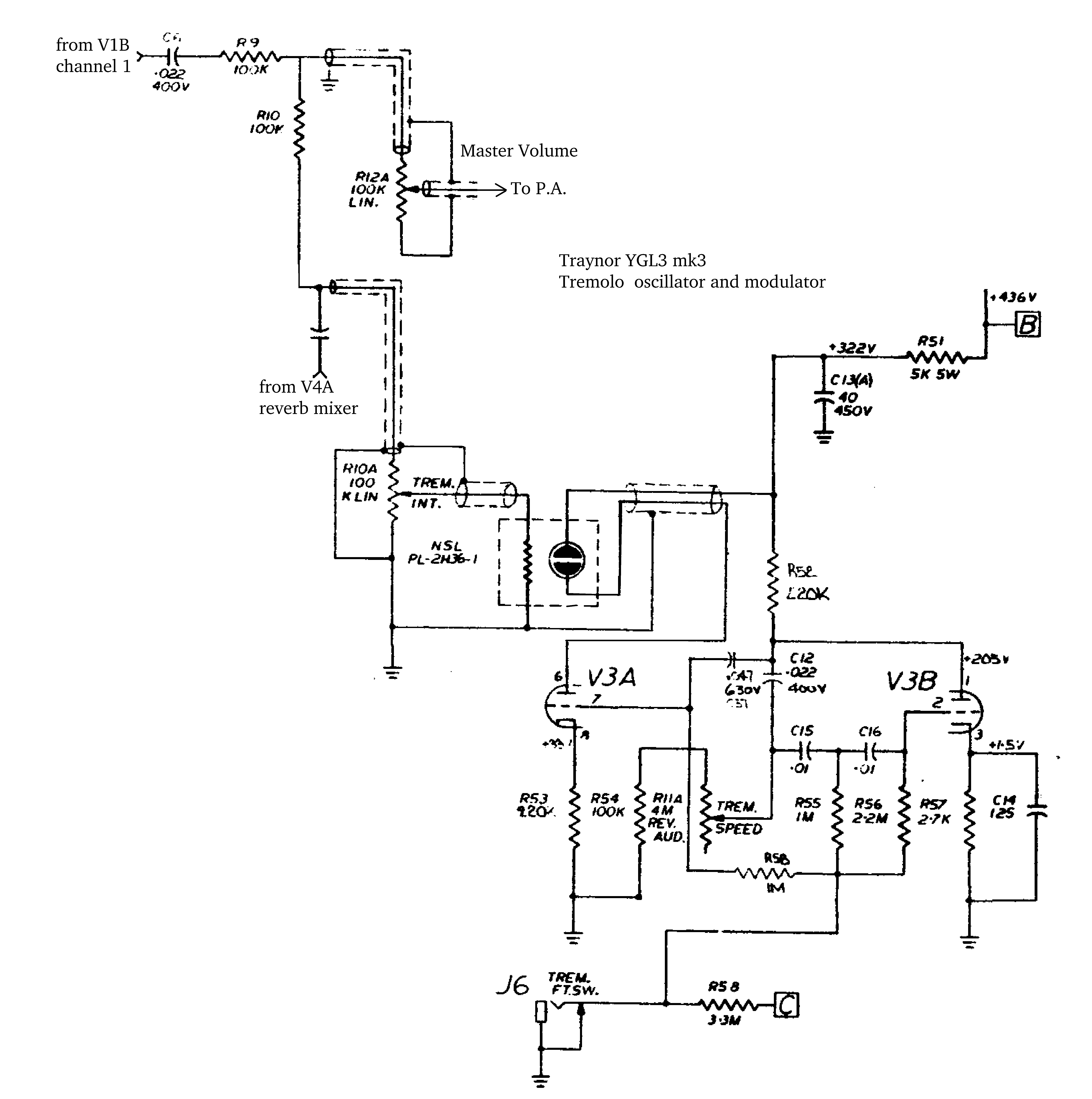
The tremolo oscillator V3B is standard. V3A anode then drives the cell which consists of a neon lamp and a cadmium sulphide resistor in a little plastic box.
|
|
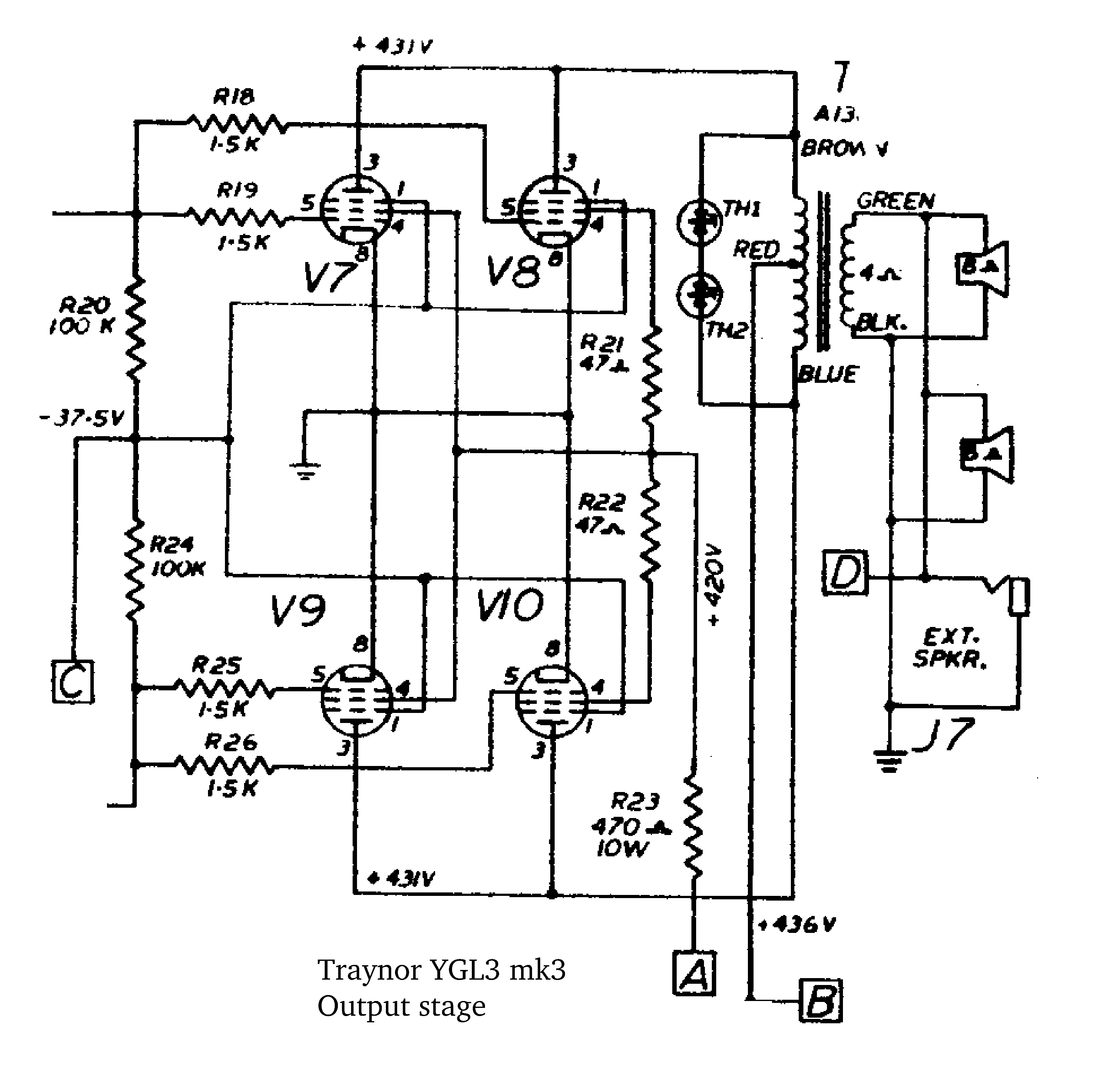
The output stage. Note the unusual screen circuit. The suppressors are connected to the fixed-bias negative supply, not to ground. The stoppers are inside the grid leaks, fairly conventional. The transformer has only one secondary, apparently 4 ohms, but there is also an EXT SPKR jack, which would put a quite heavy load on things. The components TH1 and TH2 were not present, and I'm not sure what they are. Some sort of wacky diode probably. |
|
end