![]()
![]()

|
An often-repeated story about the DC300 says that it was originally designed as a piece of lab equipment for boffins and space cadets, and later marketed for pro-audio use after Crown discovered that those were the people actually buying it. That would maybe account for some of its strange features, for example the fact that it's direct-coupled at both ends, unheard of in pro-audio applications. Certainly many were sold into the sound reinforcement business, there was little competition at the time. A few were modified to make them more suitable for the job, but most were not.
|
|
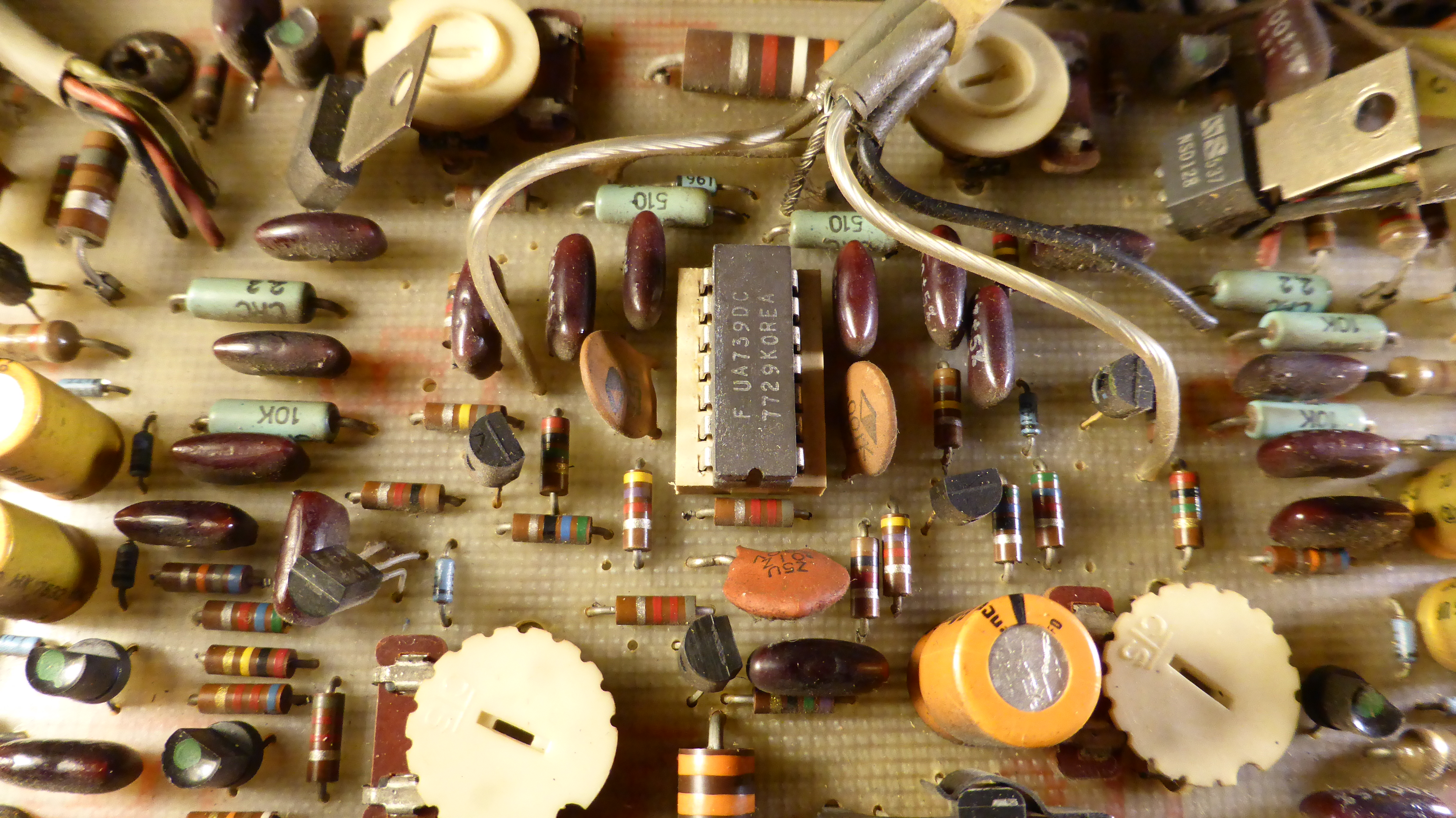
One problem with the direct-coupled input is of course that you don't necessarily know what is providing the signal or how many zeds it has. And then that is going to vary when you move the volume control. In many applications it won't matter much so long as the offset remains reasonable, but Crown have provided two trimpots on each channel, and a complicated procedure to set things up. If these trimpots go bad, it can make life a bit more exciting.
|
|
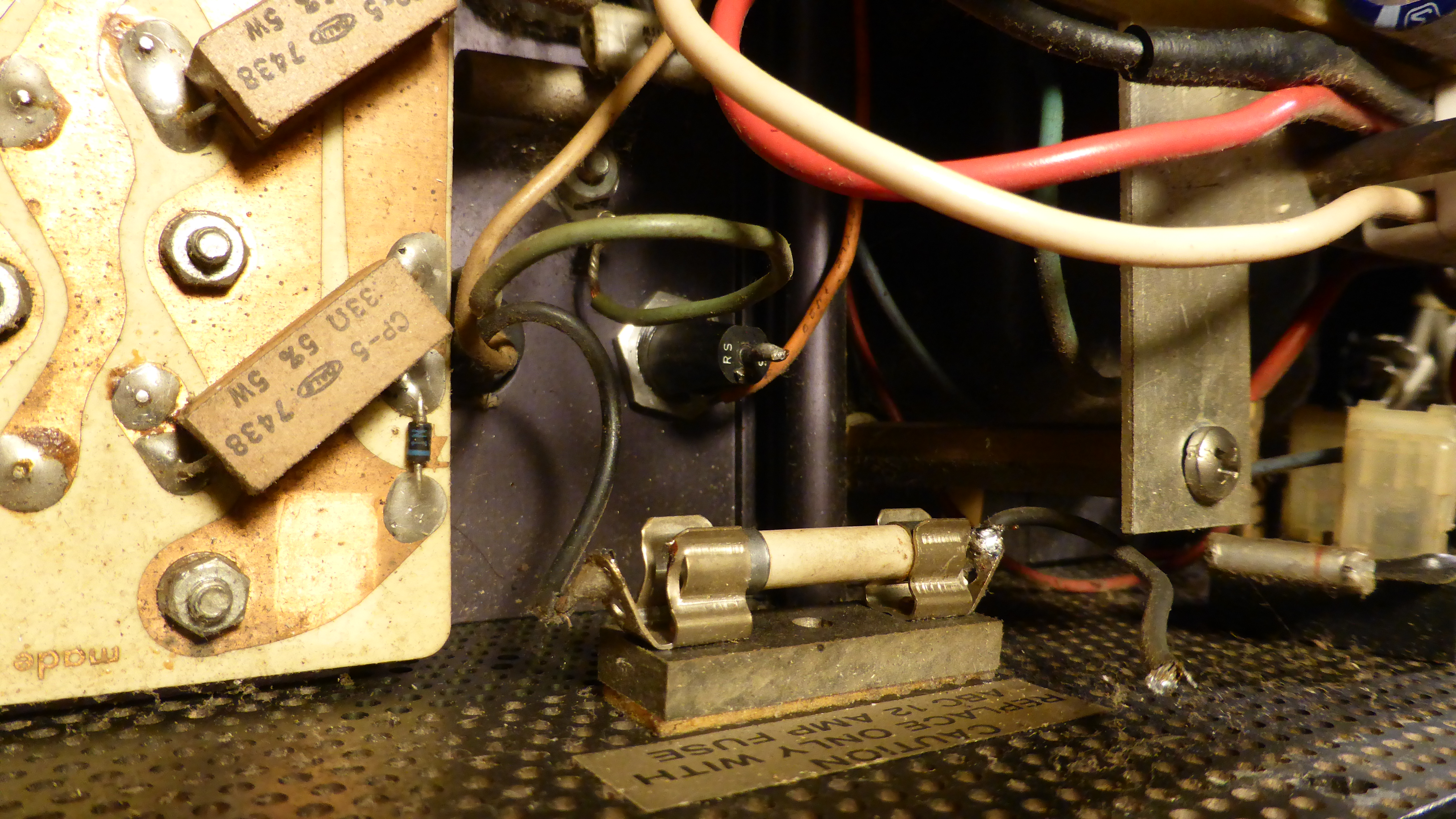
The strange main fuse arrangement has a 10A fuse in a panel socket in series with an internal 12A fuse. I'm sure there is some science behind this, some decades ago a Crown engineer explained it to me. I wish I could remember his drunken ramblings. I am going to rewire things to leave out the mystery fuse, and leave the T10A HRC in the panel socket. |
|
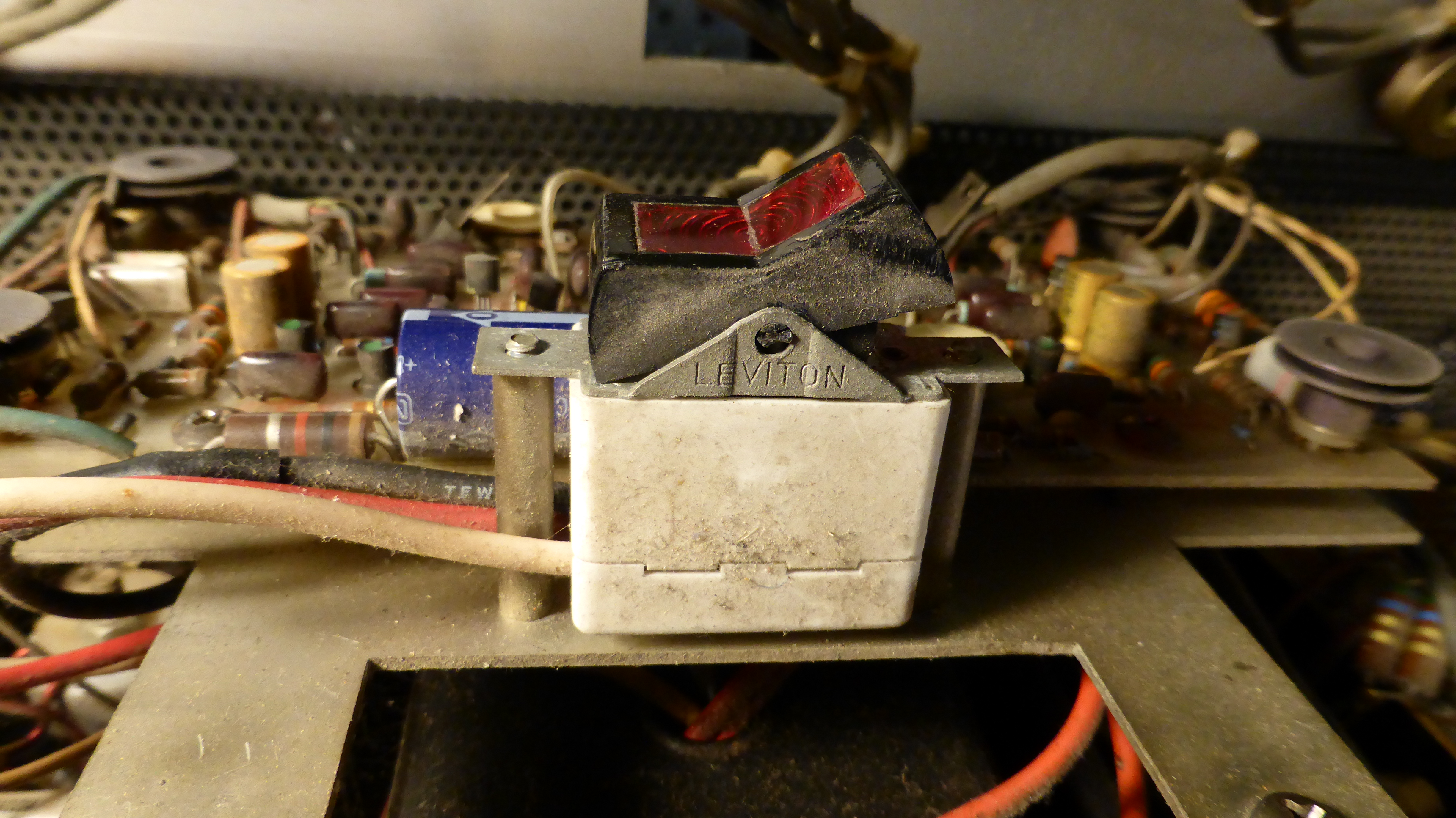
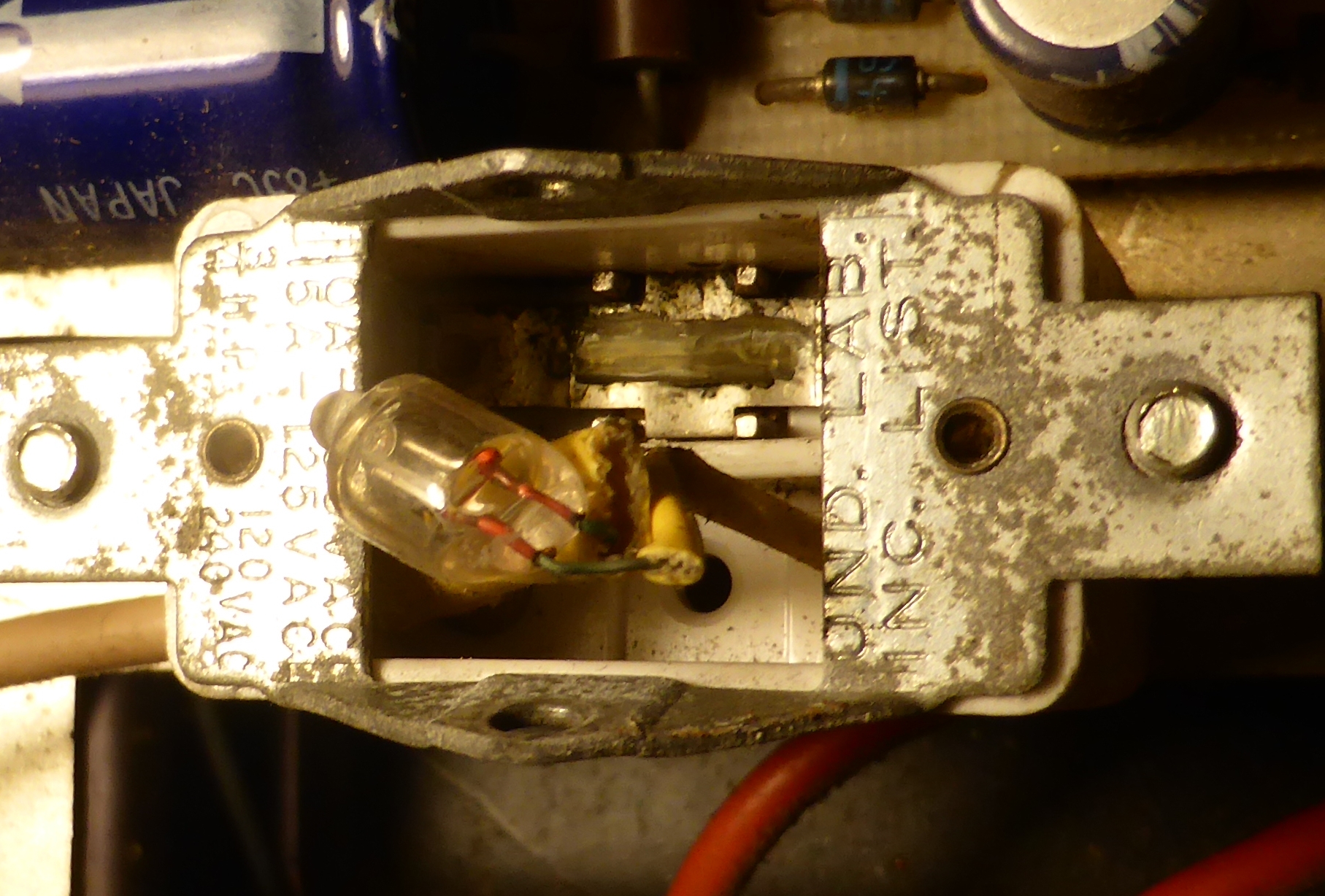
Check out this bollocks of a switch. It's designed so that the thin metal sides cut through the soft plastic rocker every time it is operated. It is about to pop apart and spill its guts. It is mounted so that it can't be removed without taking half the works out. It is a weird shape and size so I can't replace it with a proper one. I like to imagine that the designer of it is no longer with us, having died in a bizarre accident.
Fixing this is going to be the time-consuming bit of the operation. |
|
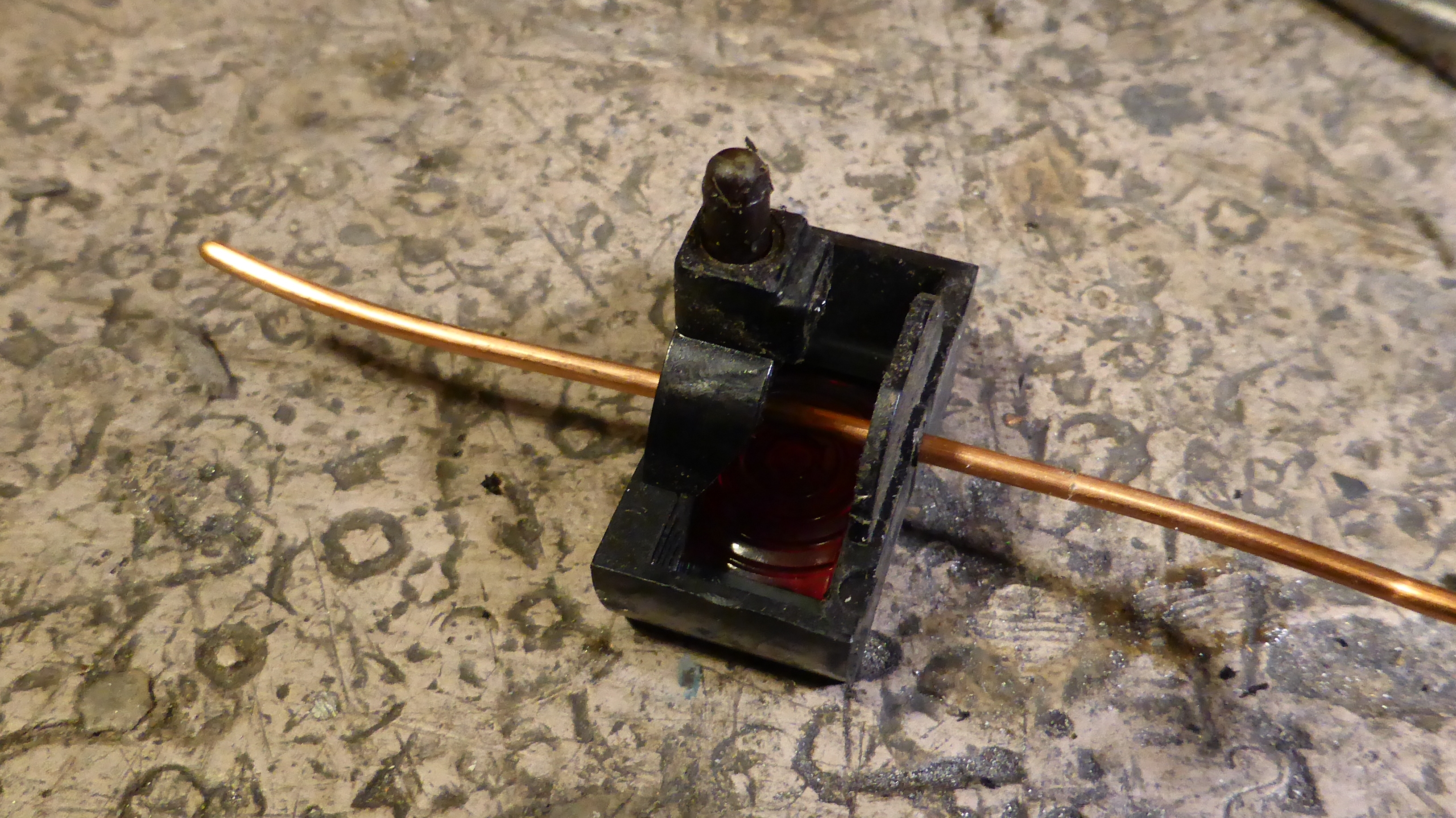
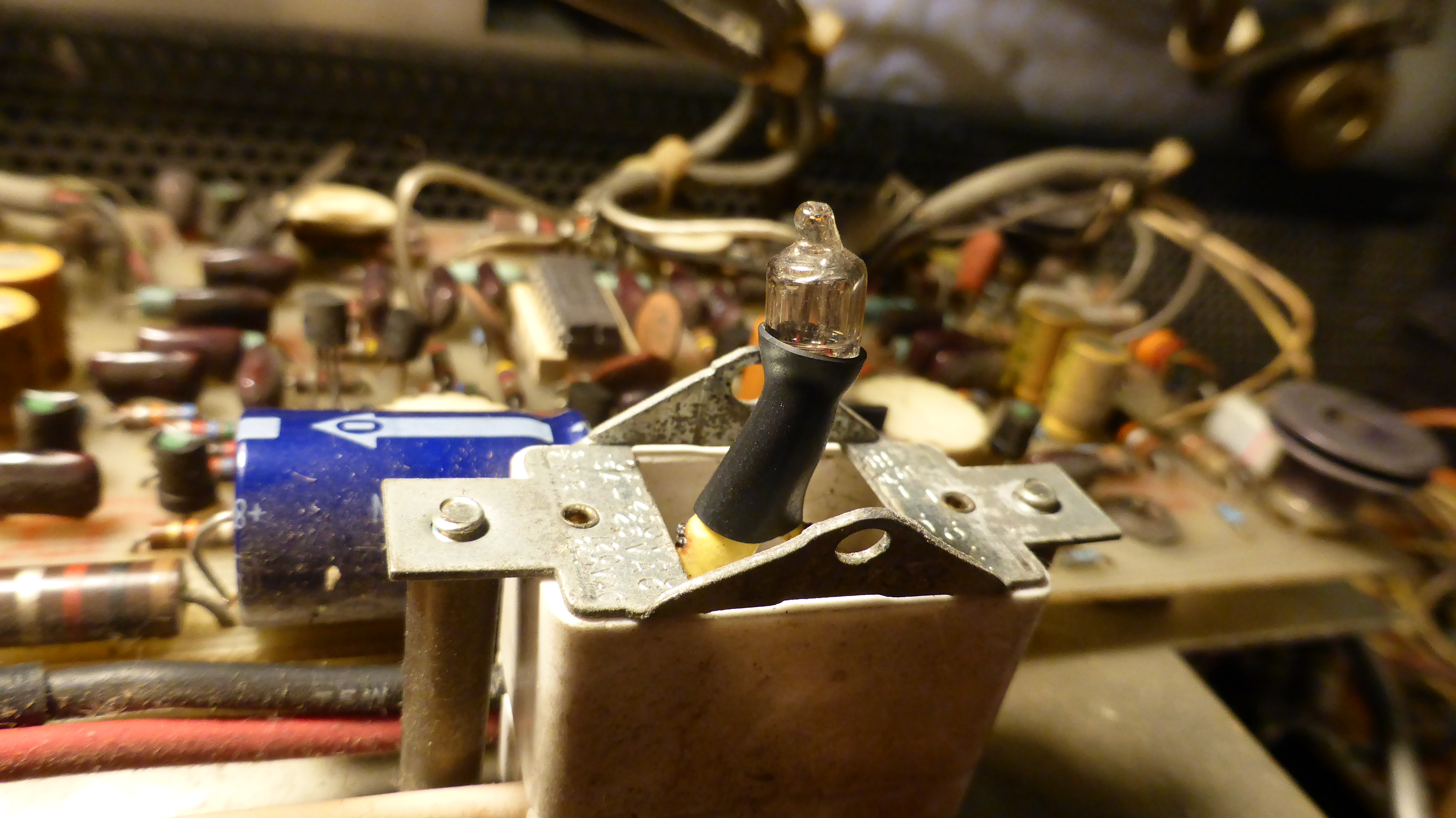
I drill holes in the rocker and use some wire. |
|
Messy. |
|
Try to make the neon a bit less messy with some shrinko. |
|
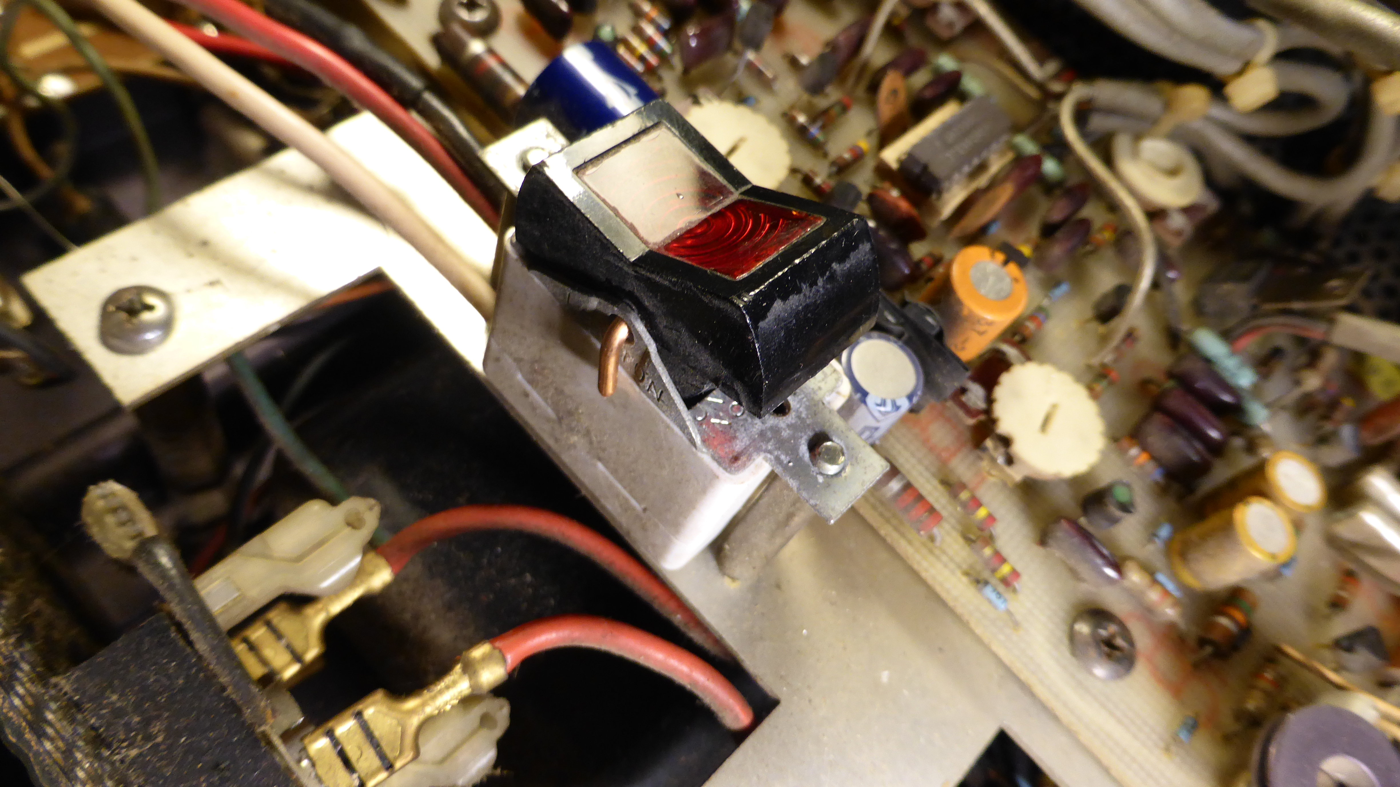
It works. |
|
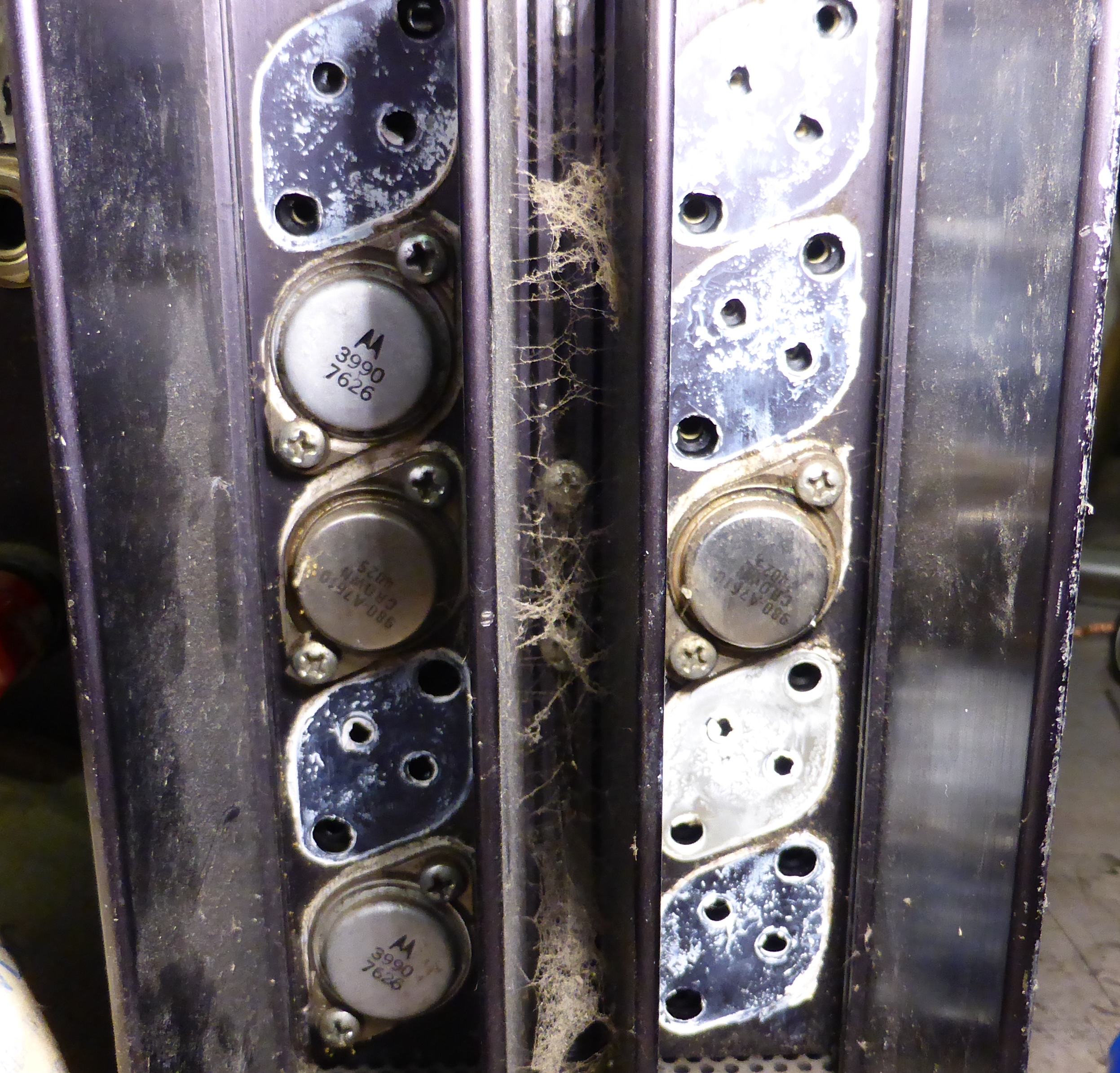
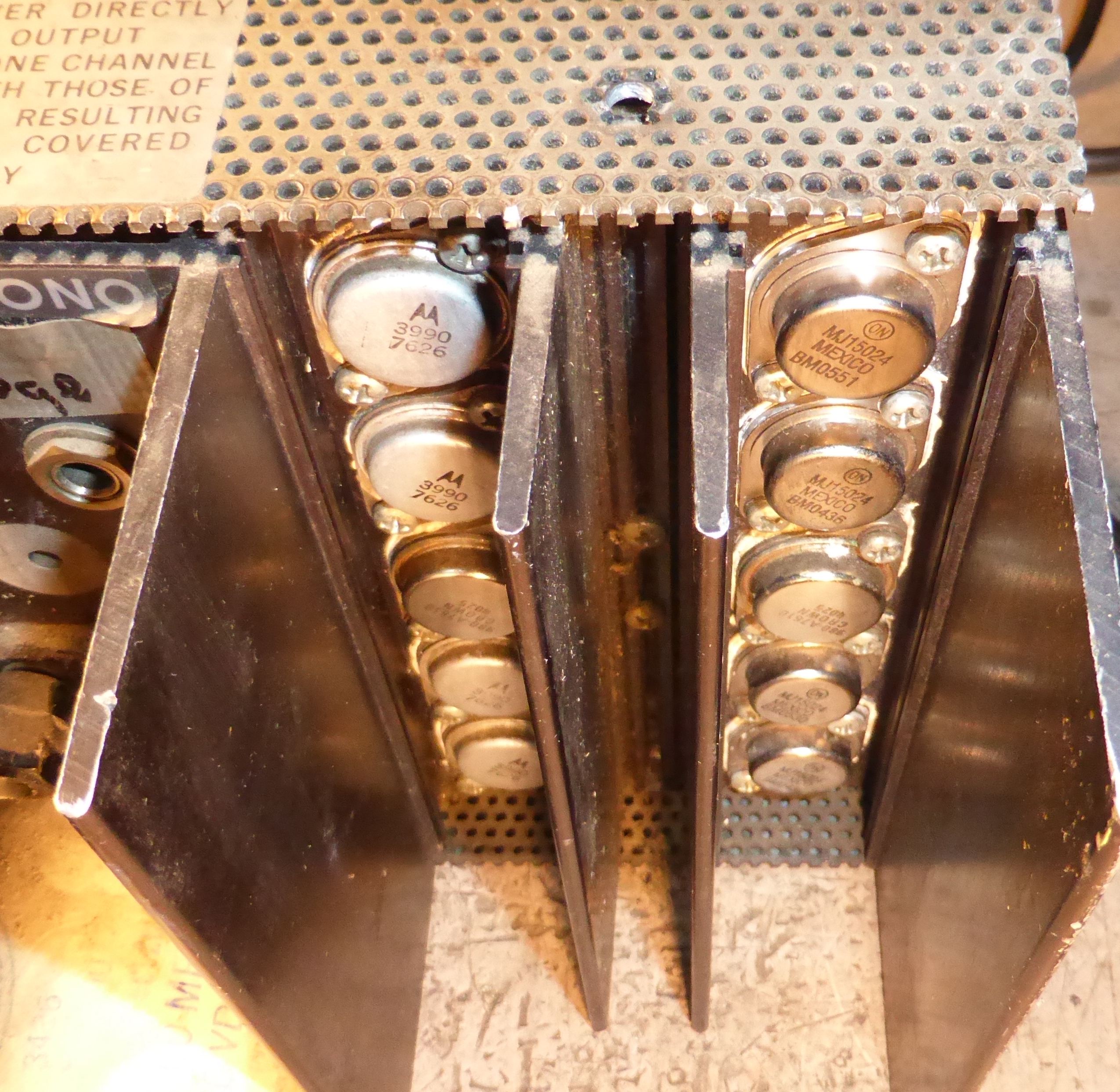
Three transistors failed, two pulling and one pushing. So I take all the transistors of the push side and fit the best two on the pull side. So that now has a set of four good original transistors. |
|
And replace the four on the push side with a matched set of 15024's. I think it was Michael Faraday who said "Always repair DC300 amps with 15024's" |
|
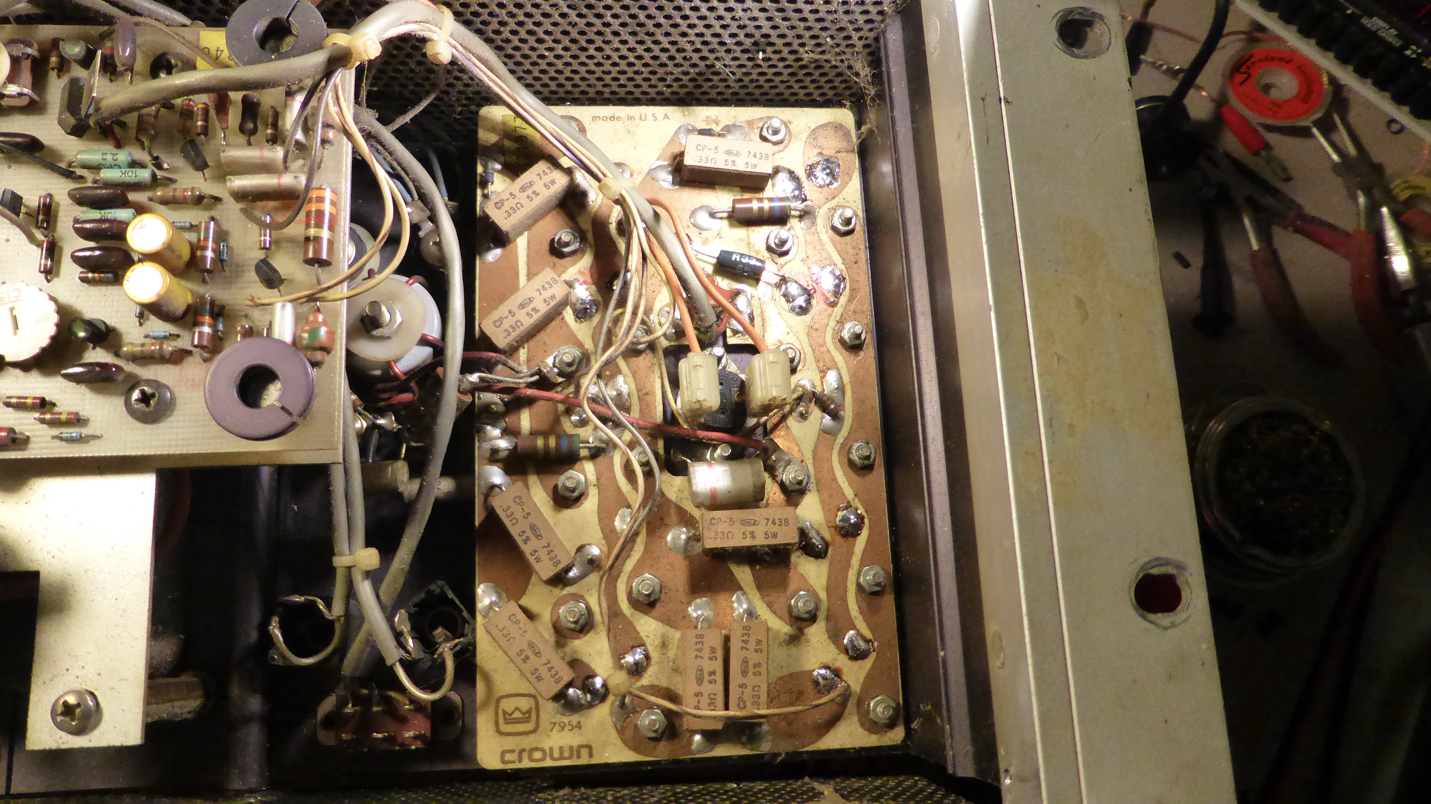
The output board has escaped damage except for just one of the emitter resistors. |

|
The three failed transistors. A bit strange that two of them have 3 written in red. |
|
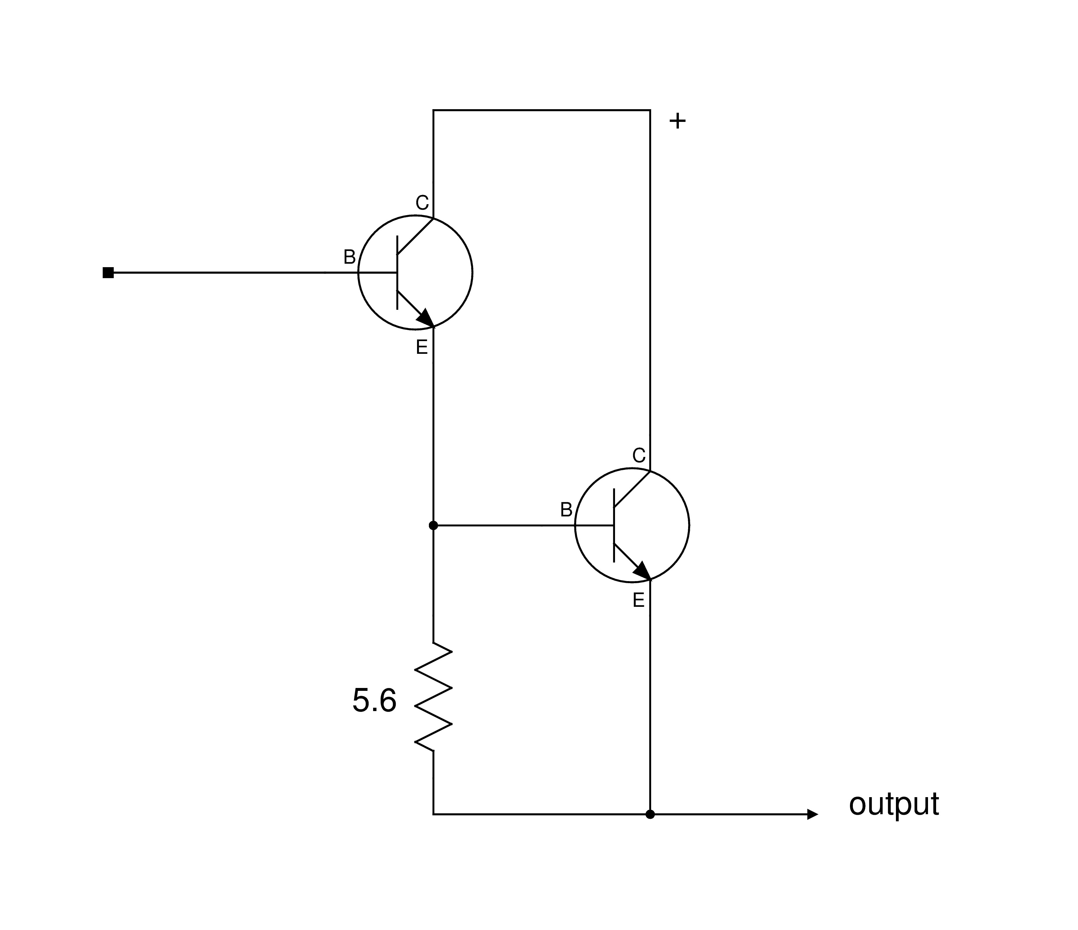
How the output stage works. The outputs don't do much until the drivers are up to about 100mA. It looks so simple but it really isn't. Many have tried to pull this off and failed. It is the real reason the circuit contains a couple of small inductors and lots more small compensation capacitors than you would expect.
|

|
Finished. I wouldn't expect any more problems for a few years. |