![]()
![]()

|
Of the hundreds of guitar amps that I have owned or repaired, this is the one that I am keeping. It is a strange old thing, but I like it. The circuit is not out of the ordinary except perhaps for the tone controls being more elaborate and effective than usual. Hum and noise are extremely low. I can't point out any particular design feature that makes it special, it seems like it just came together right.
|
|
(If you want to embiggen any picture here or on other pages, right-click on it then select view image. Or whatever your browser calls it.)
|
Schematic circuit diagrams | |
|
A redrawn schematic of "Mod CS60 Bass"This image is a png file. To see full size, right-click>view image, then click on image or ctrl-scroll to adjust size. Best printed at A3 size, but A4 will work if you have a good printer and eyesight. For A4 size pdf click here For A3 size pdf click here |
|
A schematic drawn from serial number 103This image is a png file. To see full size, right-click>view image, then click on image or ctrl-scroll to adjust size. Best printed at A3 size, but A4 will work if you have a good printer and eyesight. For A4 size pdf click here For A3 size pdf click here |
|
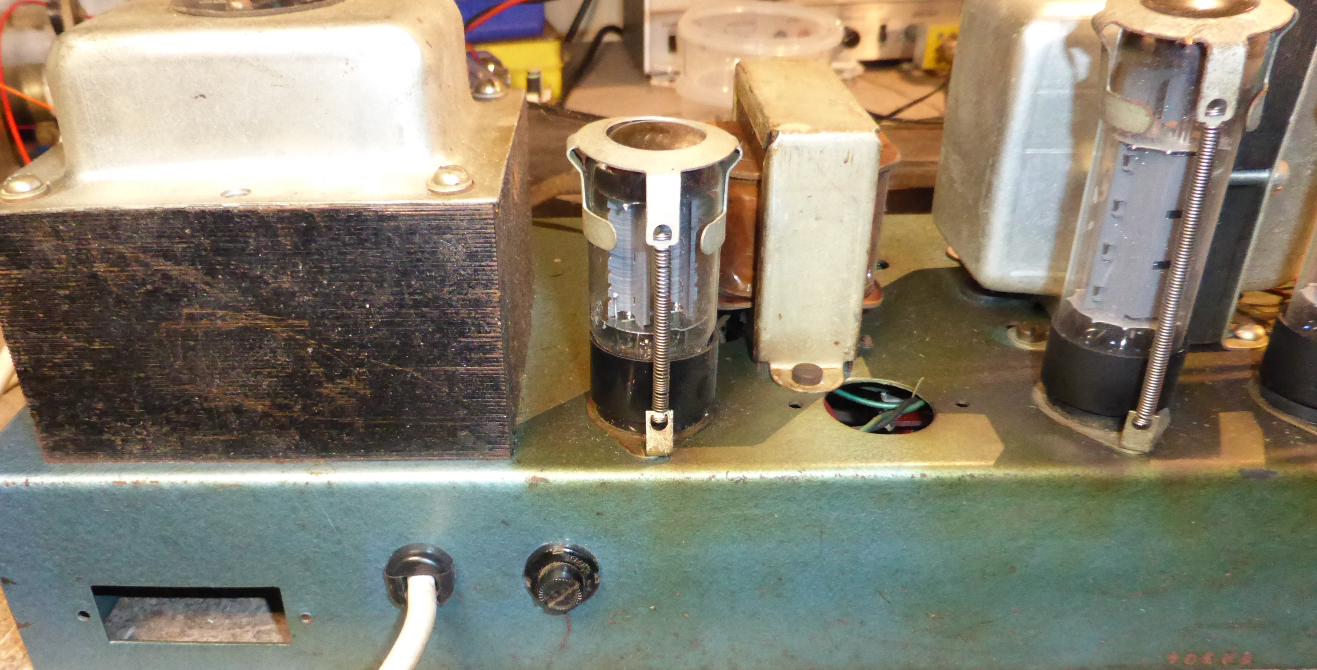
An overall view. There is a hole for a can capacitor that was never used. The back panel has an unused rectangular hole probably intended for a selector switch. |
|
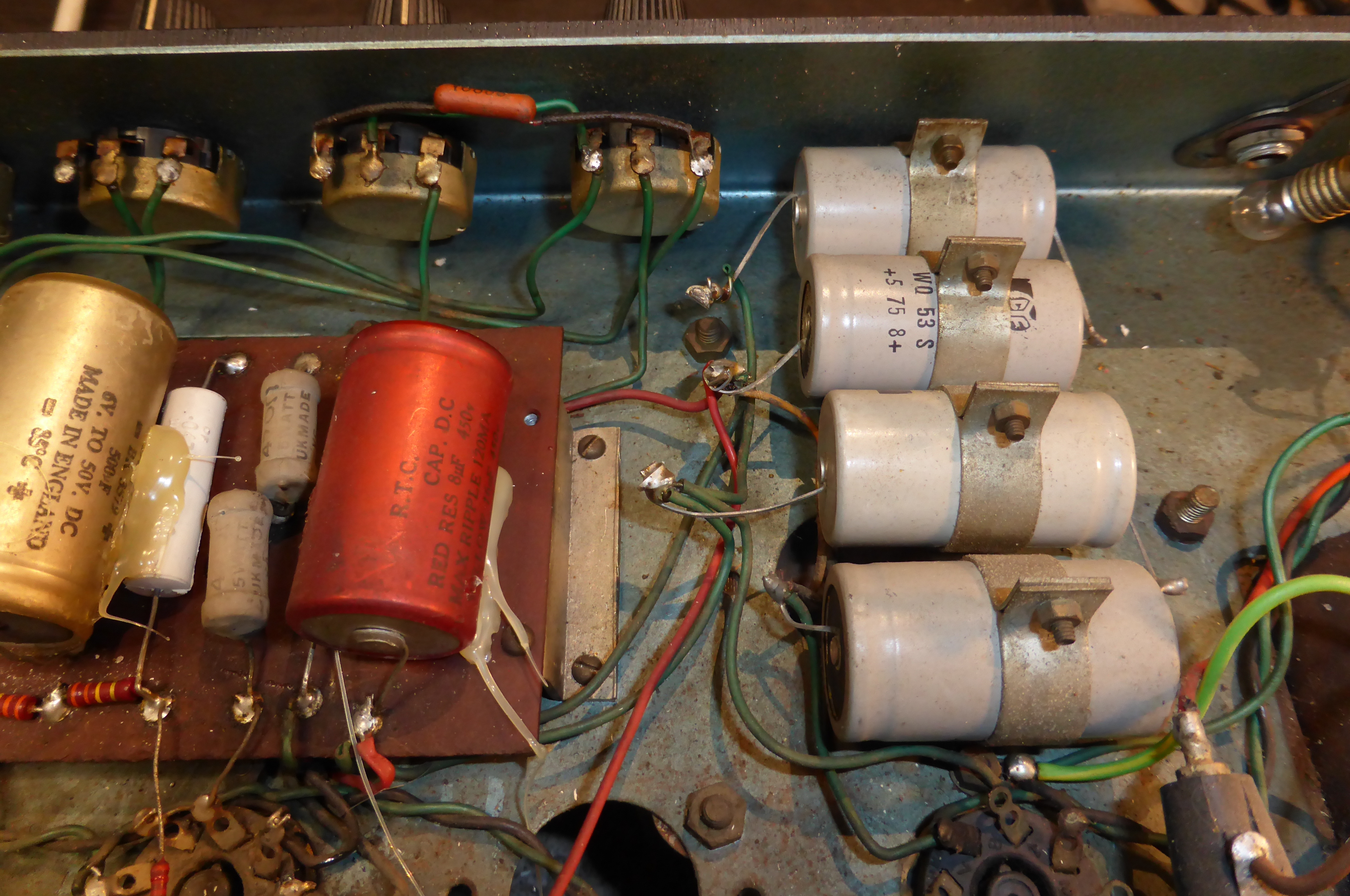
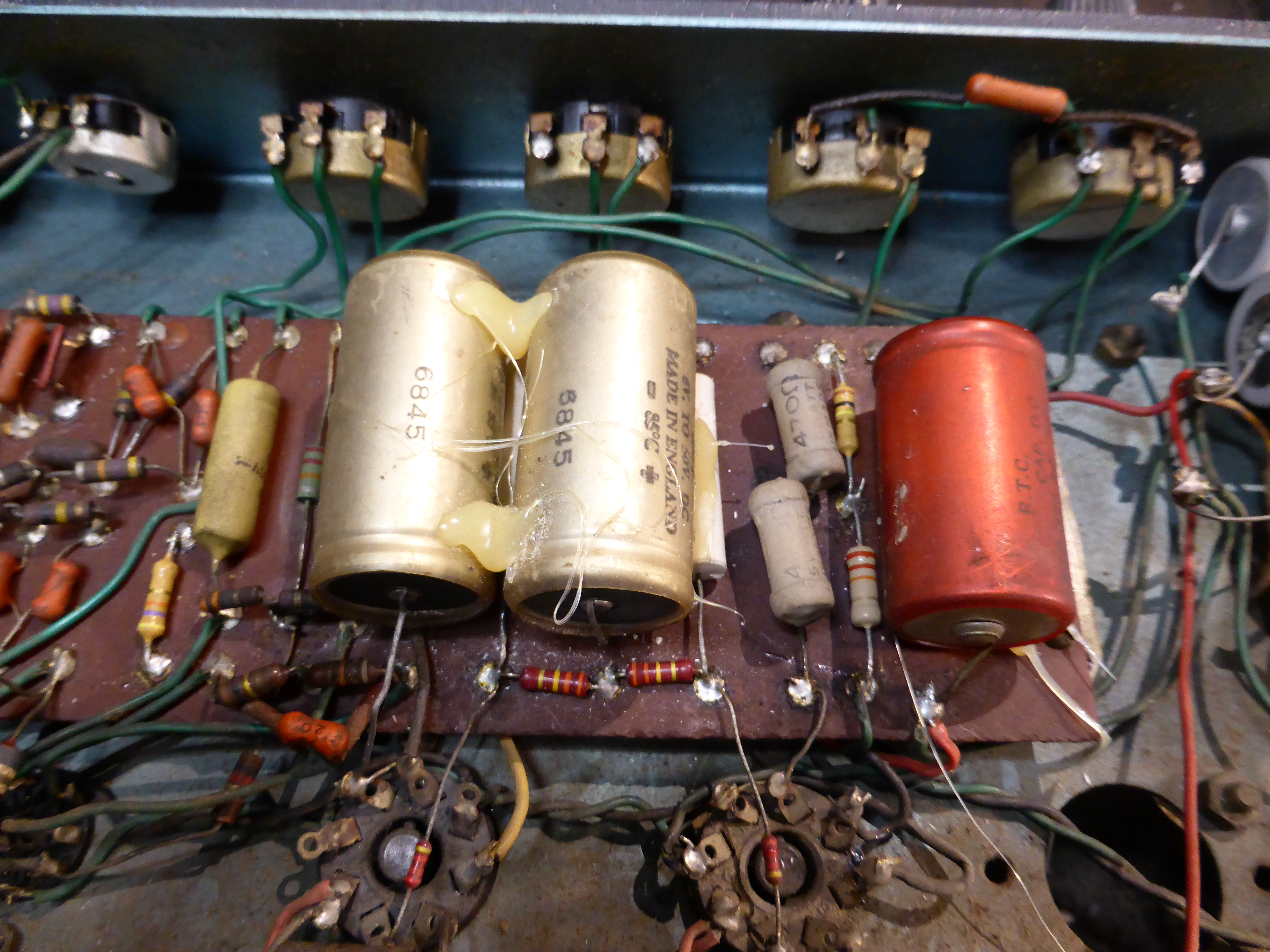
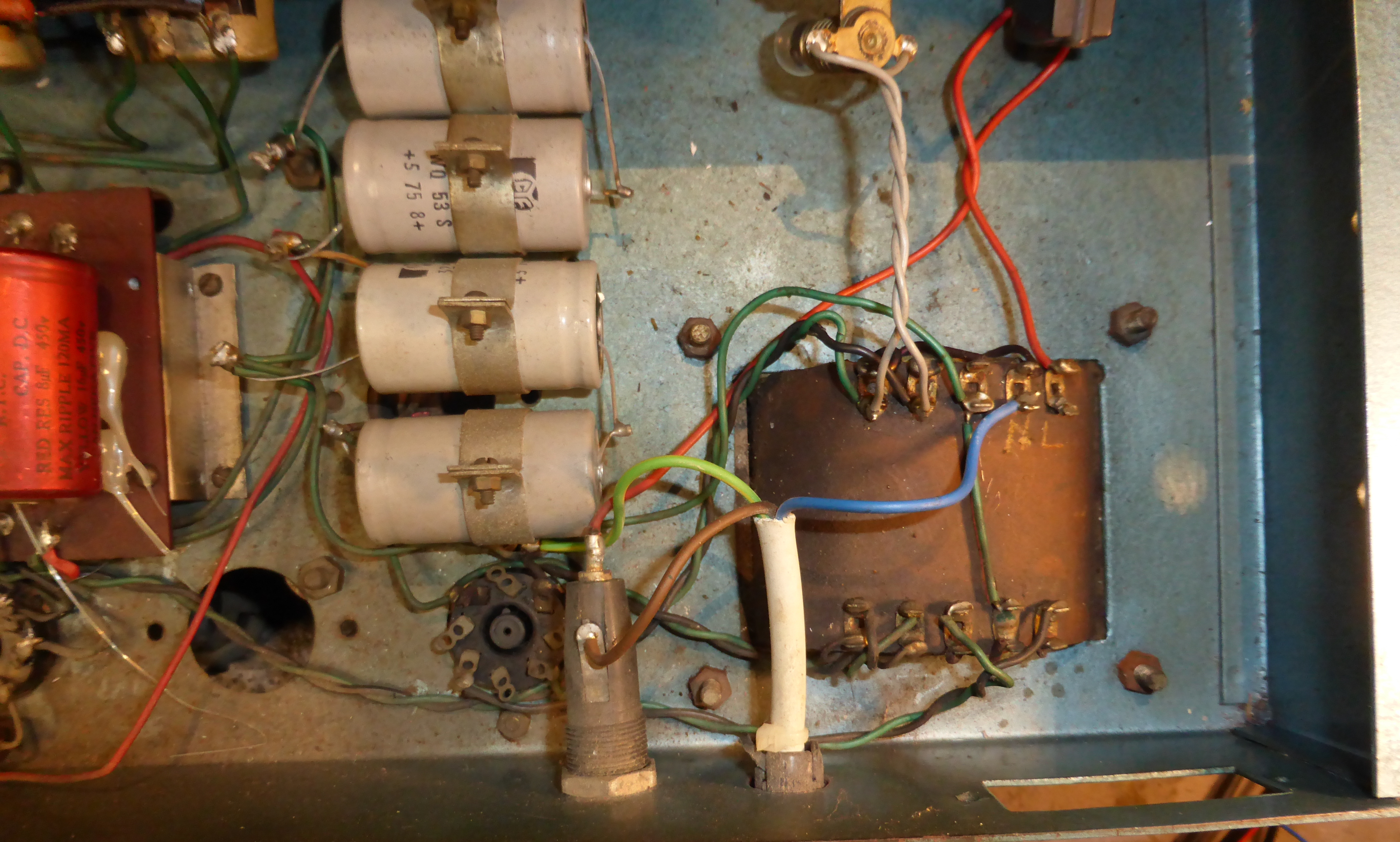
The main supply capacitors. These are not original, I think this amp was made in the early 1960's. |
|
The red capacitor is a dual, but only one half seems to be used, although the other half is fed from a 100k resistor which then goes nowhere. The o/s coupling capacitors and the cathode bypasses have been replaced in the distant past. Also a few new resistors visible here. Some hotsnotting has been done. |
|
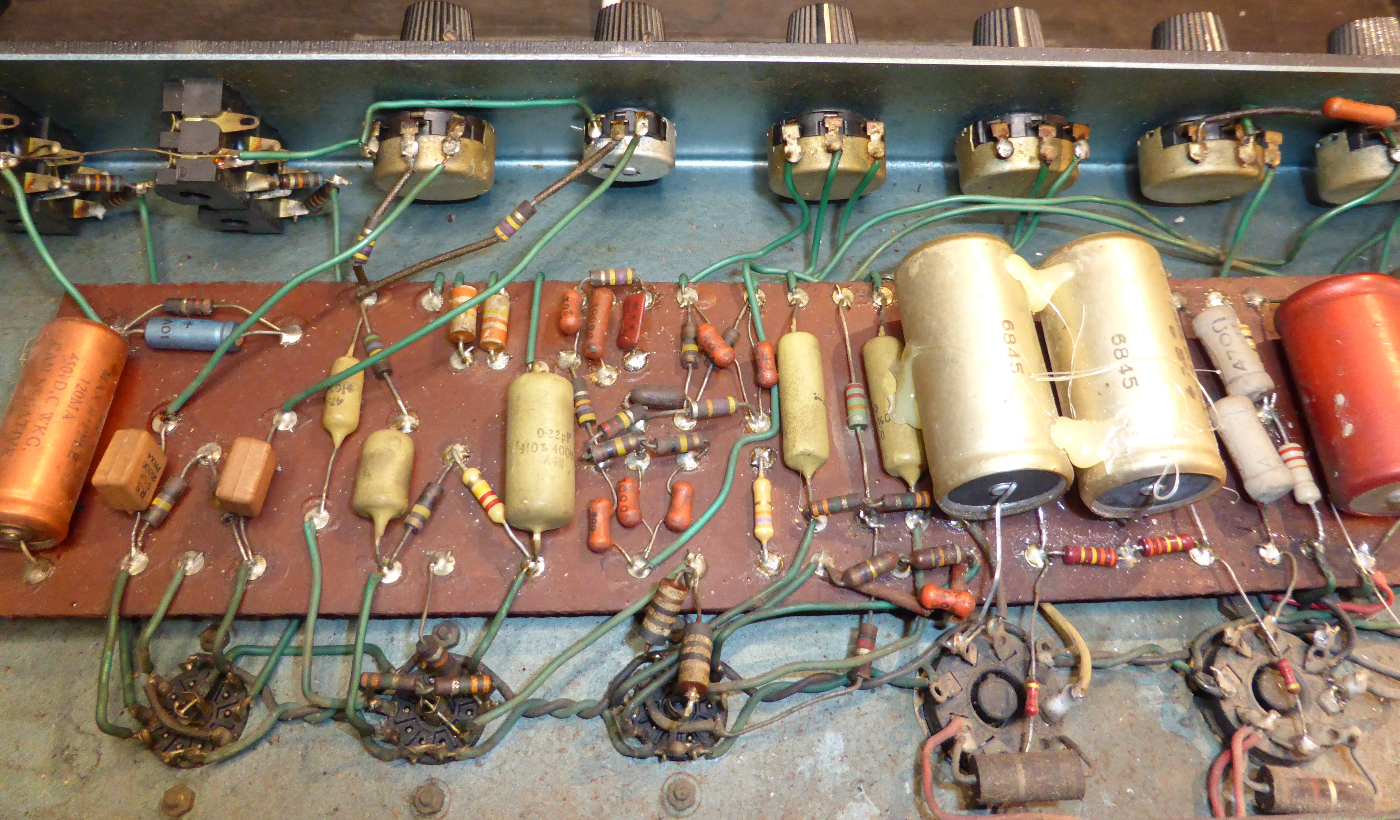
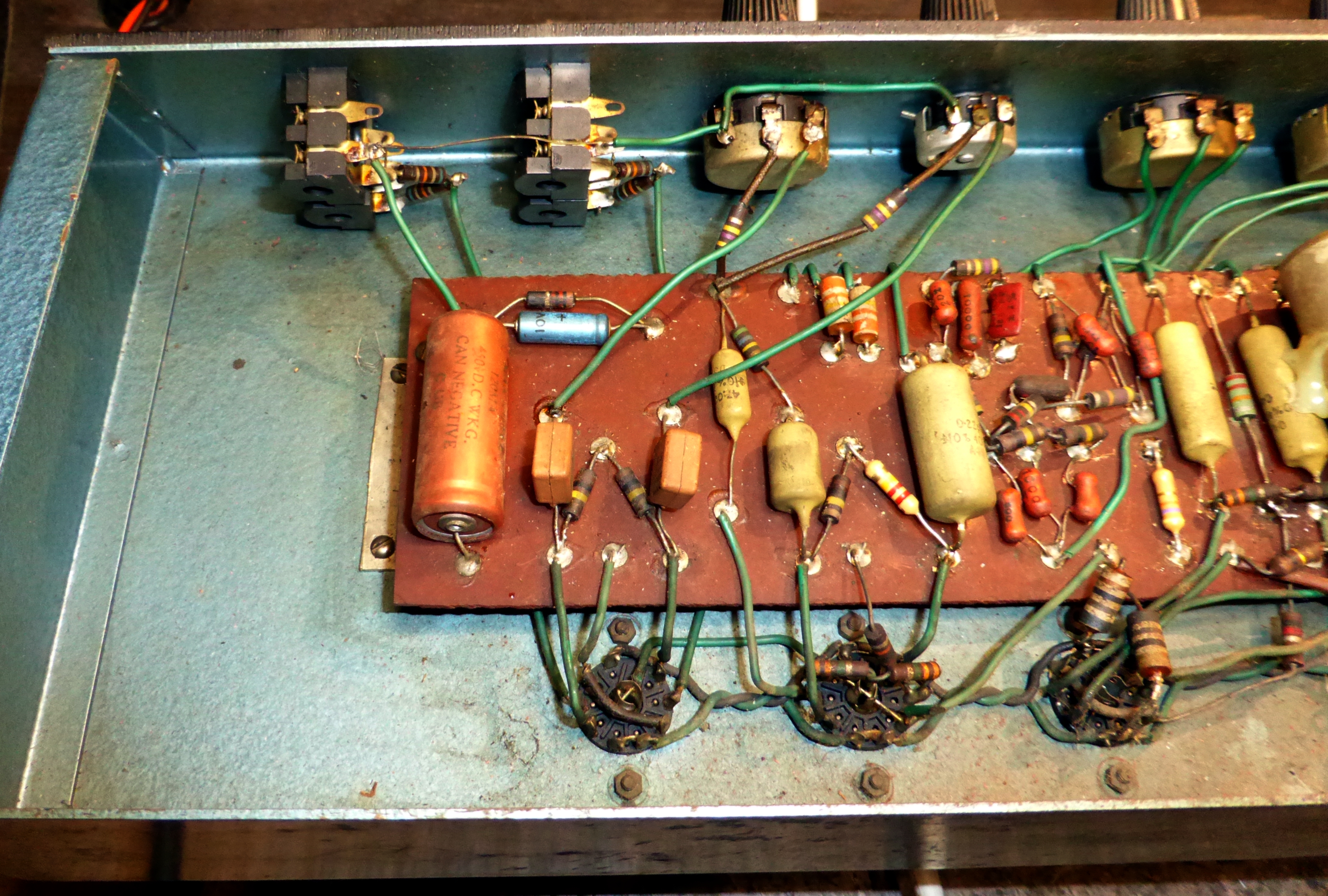
In the centre of the picture are the RC networks of the tone controls.
|
|
The two rectangular caps which feed the volume controls are the same value, 100n. In Mod CS60 one is smaller, as though they thought to provide a restriction on lower frequencies in one channel. Apparently this was intended as a bass amplifier, and the later models were dual purpose. But much like the Fender Bassman amplifier it works very well with guitar.
|
|
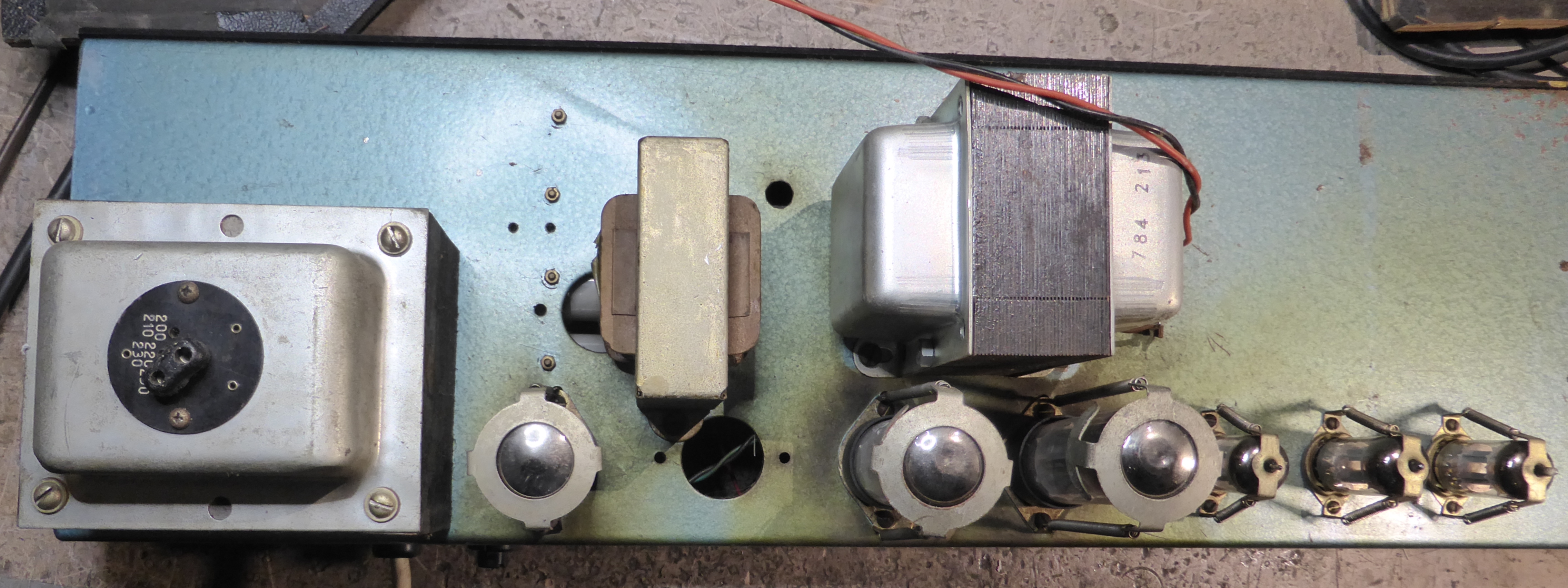
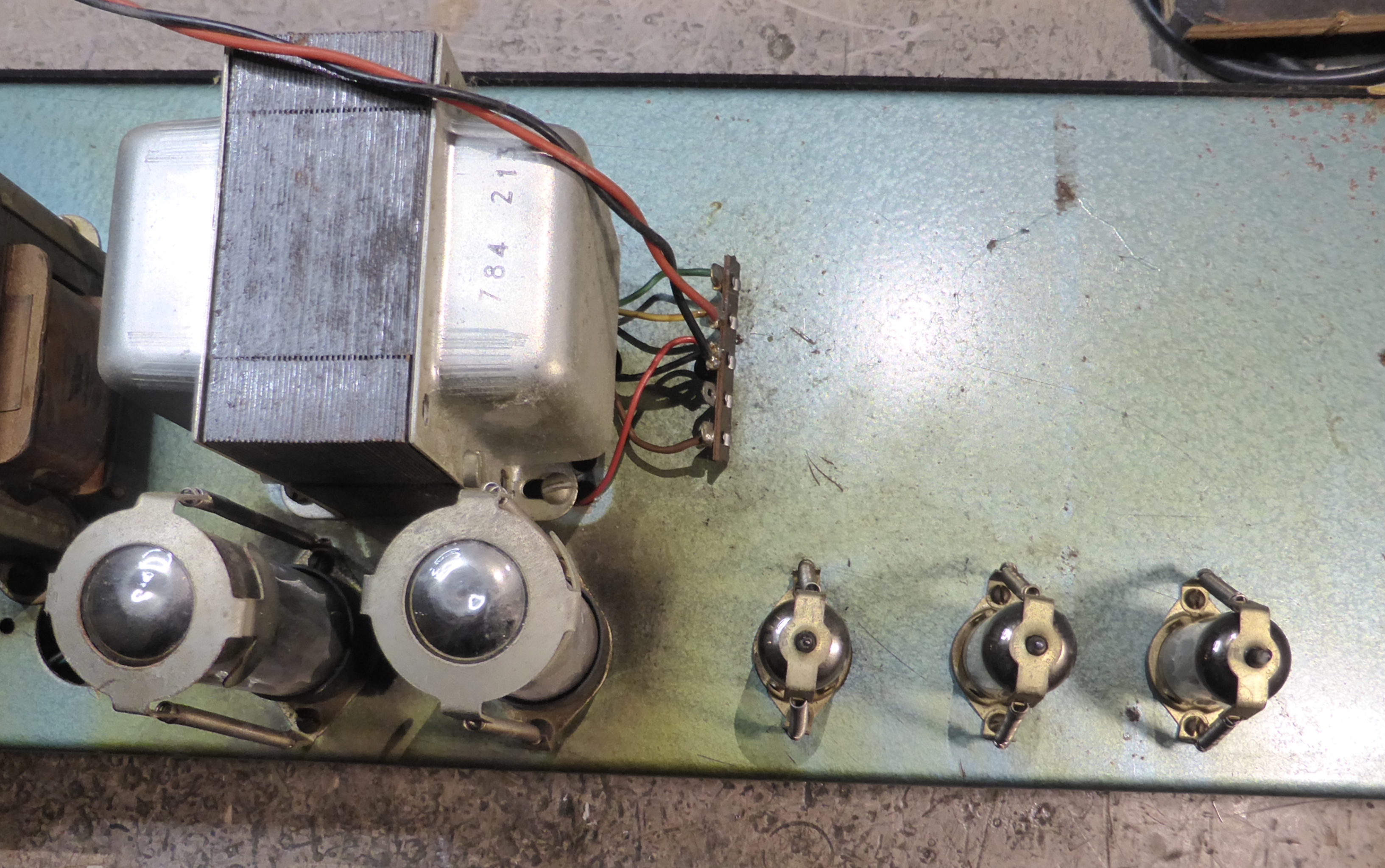
The square hole is near the power transformer, so maybe it was intended for selecting volts. But this transformer has selector plugs on its top end.
|

|
It's a mess. I have been tempted to tidy it up, but decided against it. |
|
The chassis goes in its box upside down so all the valves need their little hats on. |
|
The ohms selector is hard-wired and a complete pain in the bum if you ever need to use it. I don't.
|
|
If you like, you can put your fingers through the hole and get a big surprise from the HT winding. 425VAC, feels like much more.
|
|
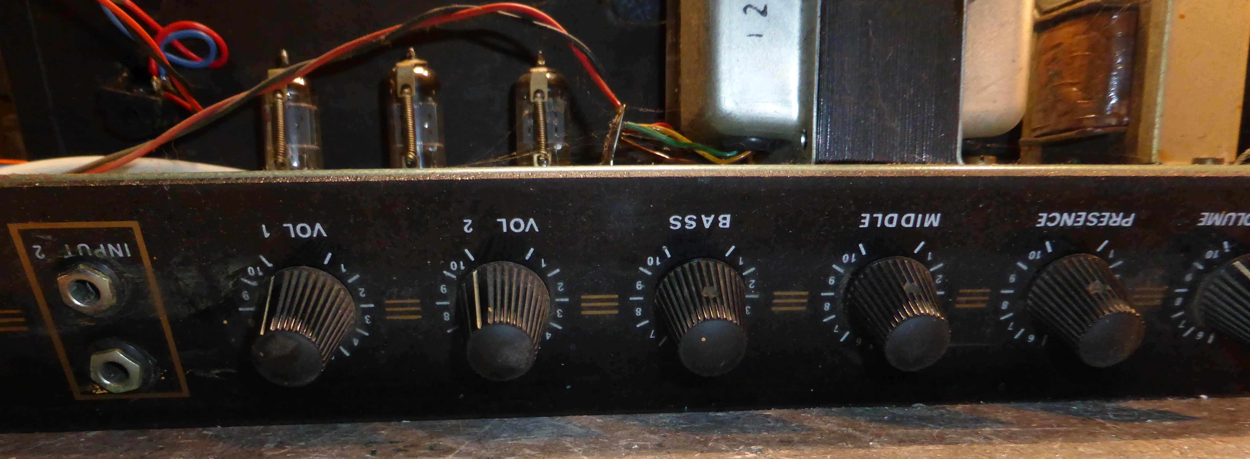
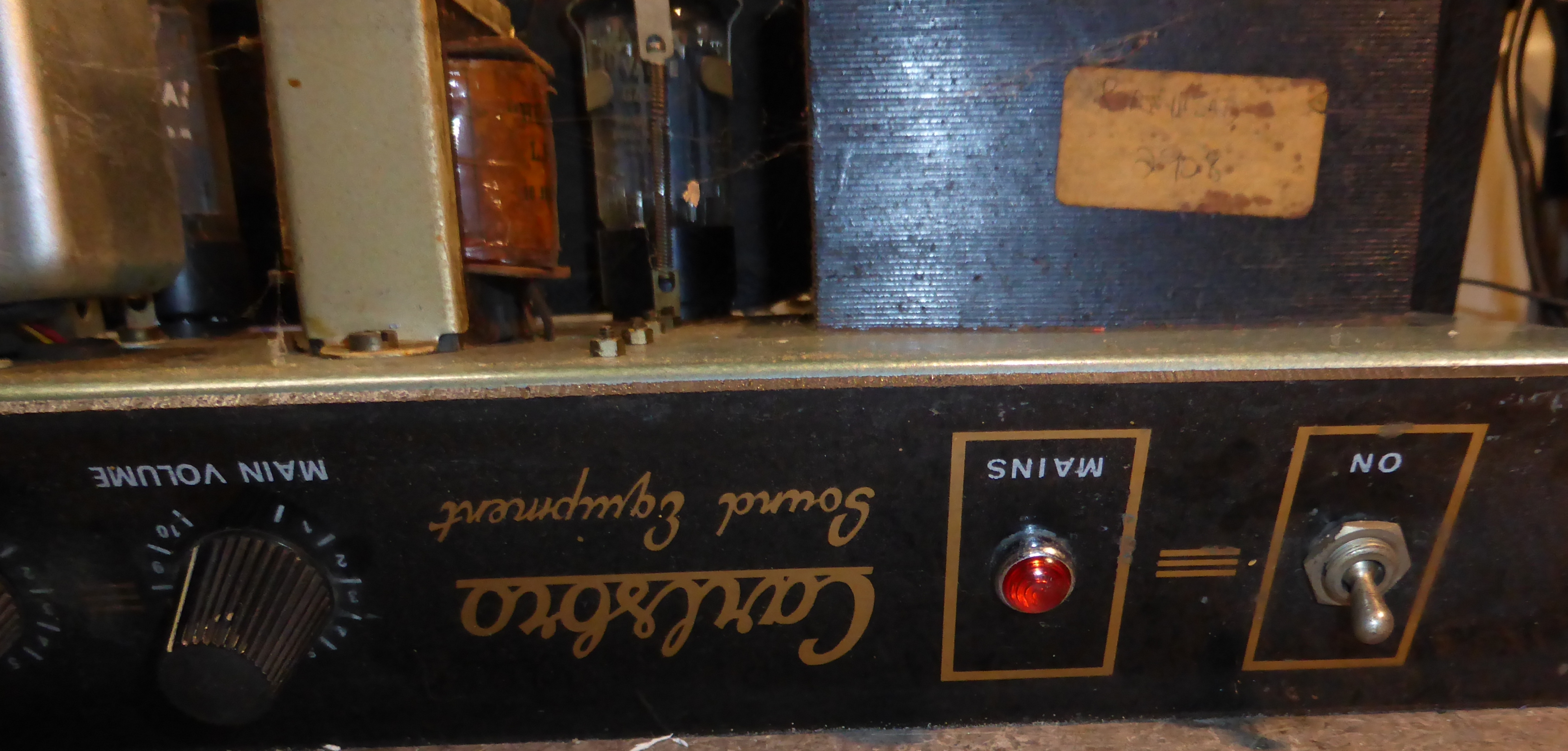
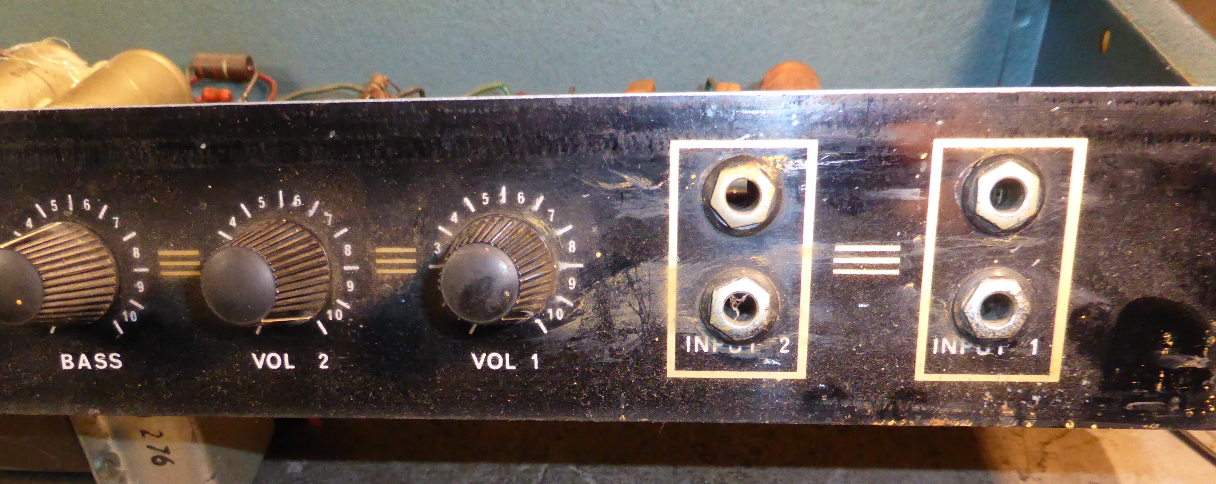
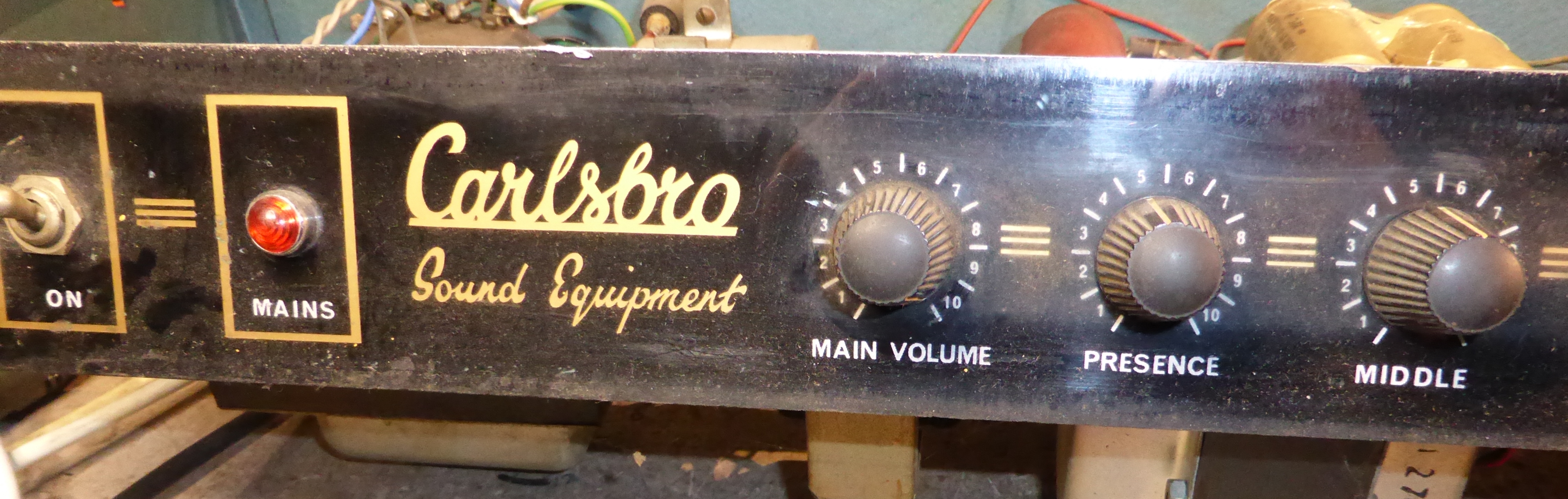
I love the knobology on this thing. |
|
|
|
|
|
end